Introduction

Contents
The Steam and Condensate Loop
How is steam generated, distributed, controlled and used? How is the condensate recycled? A basic overview of a steam system.
This Module of The Steam and Condensate Loop is intended to give a brief, non-technical overview of the steam plant. It offers an overall explanation of how the different parts of the steam plant relate to each other - and represents useful reading for anyone who is unfamiliar with the topic, prior to progressing to the next Block, or, indeed, before undertaking any form of detailed study of steam theory or steam plant equipment.
The boiler house
The boiler
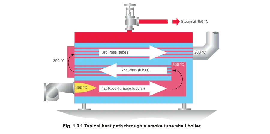
The boiler is the heart of the steam system. The typical modern packaged boiler is powered by a burner which sends heat into the boiler tubes.
The hot gases from the burner pass backwards and forwards up to 3 times through a series of tubes to gain the maximum transfer of heat through the tube surfaces to the surrounding boiler water. Once the water reaches saturation temperature (the temperature at which it will boil at that pressure) bubbles of steam are produced, which rise to the water surface and burst. The steam is released into the space above, ready to enter the steam system. The stop or crown valve isolates the boiler and its steam pressure from the process or plant.
If steam is pressurised, it will occupy less space. Steam boilers are usually operated under pressure, so that more steam can be produced by a smaller boiler and transferred to the point of use using small bore pipework. When required, the steam pressure is reduced at the point of use.
As long as the amount of steam being produced in the boiler is as great as that leaving the boiler, the boiler will remain pressurised. The burner will operate to maintain the correct pressure. This also maintains the correct steam temperature, because the pressure and temperature of saturated steam are directly related.
The boiler has a number of fittings and controls to ensure that it operates safely, economically, efficiently and at a consistent pressure.
Feedwater
The quality of water which is supplied into the boiler is important. It must be at the correct temperature, usually around 80°C, to avoid thermal shock to the boiler, and to keep it operating efficiently. It must also be of the correct quality to avoid damage to the boiler.
Ordinary untreated potable water is not entirely suitable for boilers and can quickly cause them to foam and scale up. The boiler would become less efficient and the steam would become dirty and wet. The life of the boiler would also be reduced.
The water must therefore be treated with chemicals to reduce the impurities it contains.
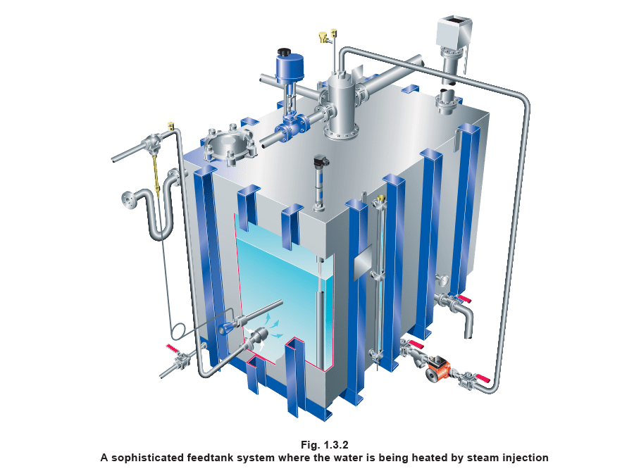
Both feedwater treatment and heating take place in the feedtank, which is usually situated high above the boiler. The feedpump will add water to the boiler when required. Heating the water in the feedtank also reduces the amount of dissolved oxygen in it. This is important, as oxygenated water is corrosive.
Blowdown
Chemical dosing of the boiler feedwater will lead to the presence of suspended solids in the boiler. These will inevitably collect in the bottom of the boiler in the form of sludge, and are removed by a process known as bottom blowdown. This can be done manually - the boiler attendant will use a key to open a blowdown valve for a set period of time, usually twice a day.
Other impurities remain in the boiler water after treatment in the form of dissolved solids. Their concentration will increase as the boiler produces steam and consequently the boiler needs to be regularly purged of some of its contents to reduce the concentration. This is called control of total dissolved solids (TDS control). This process can be carried out by an automatic system which uses either a probe inside the boiler, or a small sensor chamber containing a sample of boiler water, to measure the TDS level in the boiler. Once the TDS level reaches a set point, a controller signals the blowdown valve to open for a set period of time. The lost water is replaced by feedwater with a lower TDS concentration, consequently the overall boiler TDS is reduced.
Level control
If the water level inside the boiler were not carefully controlled, the consequences could be catastrophic. If the water level drops too low and the boiler tubes are exposed, the boiler tubes could overheat and fail, causing an explosion. If the water level becomes too high, water could enter the steam system and upset the process.
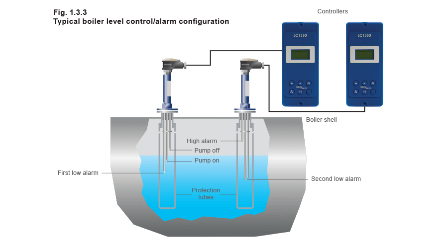
For this reason, automatic level controls are used. To comply with legislation, level control systems also incorporate alarm functions which will operate to shut down the boiler and alert attention if there is a problem with the water level. A common method of level control is to use probes which sense the level of water in the boiler. At a certain level, a controller will send a signal to the feedpump which will operate to restore the water level, switching off when a predetermined level is reached. The probe will incorporate levels at which the pump is switched on and off, and at which low or high level alarms are activated. Alternative systems use floats.
The flow of steam to the plant
When steam condenses, its volume is dramatically reduced, which results in a localised reduction in pressure. This pressure drop through the system creates the flow of steam through the pipes.
The steam generated in the boiler must be conveyed through the pipework to the point where its heat energy is required. Initially there will be one or more main pipes or steam mains which carry steam from the boiler in the general direction of the steam using plant. Smaller branch pipes can then distribute the steam to the individual pieces of equipment.
Steam at high pressure occupies a lower volume than at atmospheric pressure. The higher the pressure, the smaller the bore of pipework required for distribution of a given mass of steam.
Steam quality
It is important to ensure that the steam leaving the boiler is delivered to the process in the right condition. To achieve this the pipework which carries the steam around the plant normally incorporates strainers, separators and steam traps.
A strainer is a form of sieve in the pipeline. It contains a mesh through which the steam must pass. Any passing debris will be retained by the mesh. A strainer should regularly be cleaned to avoid blockage.
Debris should be removed from the steam flow because it can be very damaging to plant, and may also contaminate the final product.
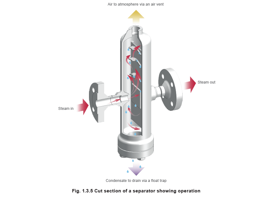
The steam should be as dry as possible to ensure it is carrying heat effectively. A separator is a body in the pipeline which contains a series of plates or baffles which interrupt the path of the steam. The steam hits the plates, and any drops of moisture in the steam collect on them, before draining from the bottom of the separator.
Steam passes from the boiler into the steam mains. Initially the pipework is cold and heat is transferred to it from the steam. The air surrounding the pipes is also cooler than the steam, so the pipework will begin to lose heat to the air. Insulation fitted around the pipe will reduce this heat loss considerably.
When steam from the distribution system enters the steam using equipment the steam will again give up energy by: a) warming up the equipment and b) continuing to transfer heat to the process. As steam loses heat, it turns back into water. Inevitably the steam begins to do this as soon as it leaves the
boiler. The water which forms is known as condensate, which tends to run to the bottom of the pipe and is carried along with the steam flow. This must be removed from the lowest points in the distribution pipework for several reasons:
- Condensate does not transmit heat effectively. A film of condensate inside plant will reduce the efficiency with which heat is transferred.
- When air dissolves into condensate, it becomes corrosive.
- Accumulated condensate can cause noisy and damaging waterhammer.
- Inadequate drainage leads to leaking joints.
A device known as a steam trap is used to release condensate from the pipework whilst preventing the steam from escaping from the system. It can do this in several ways:
- A float trap uses the difference in density between steam and condensate to operate a valve. As condensate enters the trap, a float is raised and the float lever mechanism opens the main valve to allow condensate to drain. When the condensate flow reduces the float falls and closes the main valve, thus preventing the escape of steam
- Thermodynamic traps contain a disc which opens to condensate and closes to steam.
- In bimetallic thermostatic traps, a bimetallic element uses the difference in temperature between steam and condensate to operate the main valve.
- In balanced pressure thermostatic traps, a small liquid filled capsule which is sensitive to heat operates the valve.
Once the steam has been employed in the process, the resulting condensate needs to be drained from the plant and returned to the boiler house. This process will be considered later in this Module.
Pressure reduction
As mentioned before, steam is usually generated at high pressure, and the pressure may have to be reduced at the point of use, either because of the pressure limitations of the plant, or the temperature limitations of the process.
This is achieved using a pressure reducing valve.
Steam at the point of use
A large variety of steam using plant exists. A few examples are described below:
- Jacketed pan - Large steel or copper pans used in the food and other industries to boil substances - anything from prawns to jam. These large pans are surrounded by a jacket filled with steam, which acts to heat up the contents.
- Autoclave - A steam-filled chamber used for sterilisation purposes, for example medical equipment, or to carry out chemical reactions at high temperatures and pressures, for example the curing of rubber.
- Heater battery - For space heating, steam is supplied to the coils in a heater battery. The air to be heated passes over the coils.
- Process tank heating - A steam filled coil in a tank of liquid used to heat the contents to the desired temperature.
- Vulcaniser - A large receptacle filled with steam and used to cure rubber.
- Corrugator - A series of steam heated rollers used in the corrugation process in the production of cardboard.
- Heat exchanger - For heating liquids for domestic/industrial use.
Control of the process
Any steam using plant will require some method to control the flow of steam. A constant flow of steam at the same pressure and temperature is often not what is required – a gradually increasing flow will be needed at start-up to gently warm the plant, and once the process reaches the desired temperature, the flow must be reduced.
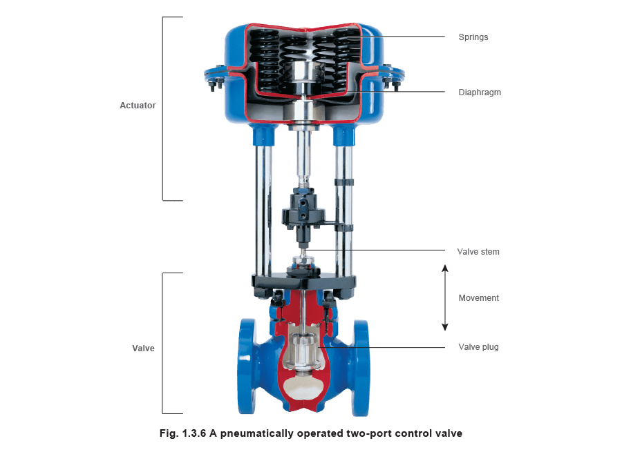
Control valves are used to control the flow of steam. The actuator, see Figure 1.3.6, is the device that applies the force to open or close the valve. A sensor monitors conditions in the process, and transmits information to the controller. The controller compares the process condition with the set value and sends a corrective signal to the actuator, which adjusts the valve setting.
A variety of control types exist:
- Pneumatically actuated valves - Compressed air is applied to a diaphragm in the actuator to open or close the valve.
- Electrically actuated valves - An electric motor actuates the valve.
- Self-acting - There is no controller as such - the sensor has a liquid fill which expands and contracts in response to a change in process temperature. This action applies force to open or close the valve.
Condensate removal from plant
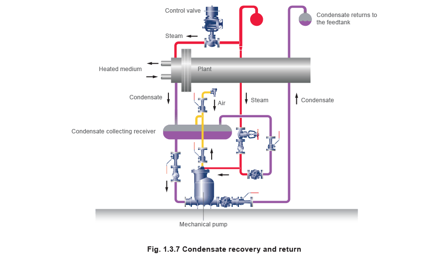
Often, the condensate which forms will drain easily out of the plant through a steam trap. The condensate enters the condensate drainage system. If it is contaminated, it will probably be sent to drain. If not, the valuable heat energy it contains can be retained by returning it to the boiler feedtank. This also saves on water and water treatment costs.
Sometimes a vacuum may form inside the steam using plant. This hinders condensate drainage, but proper drainage from the steam space maintains the effectiveness of the plant. The condensate may then have to be pumped out.
Mechanical (steam powered) pumps are used for this purpose. These, or electric powered pumps, are used to lift the condensate back to the boiler feedtank.
A mechanical pump, see Figure 1.3.7, is shown draining an item of plant. As can be seen, the steam and condensate system represents a continuous loop.
Once the condensate reaches the feedtank, it becomes available to the boiler for recycling.
Energy monitoring
In today’s energy conscious environment, it is common for customers to monitor the energy consumption of their plant.
Steam flowmeters are used to monitor the consumption of steam, and used to allocate costs to individual departments or items of plant.

