The Boiler House

Contents
The Feedtank and Feedwater Conditioning
All aspects of the design, construction and operation of feedtanks and semi-deaerators, including calculations.
The importance of the boiler feedtank, where boiler feedwater and make-up water are stored and into which condensate is returned, is often underestimated. Most items of plant in the boiler house are duplicated, but it is rare to have two feedtanks and this crucial item is often the last to be considered in the design process.
The feedtank is the major meeting place for cold make-up water and condensate return. It is best if both of these, together with flash steam from the blowdown system, flow through sparge pipes installed well below the water surface in the feedwater tank. The sparge pipes must be made from stainless steel and be adequately supported.
Operating temperature
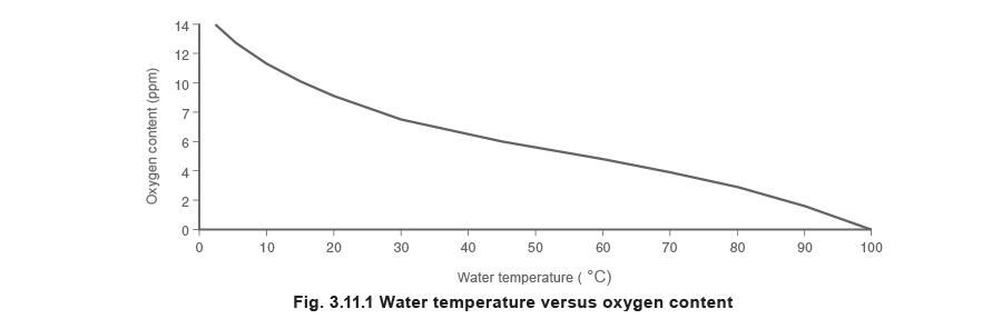
It is important that the water in the feedtank is kept at a high enough temperature to minimise the content of dissolved oxygen and other gases. The correlation between the water temperature and its oxygen content in a feedtank can be seen in Figure 3.11.1.
If a high proportion of make-up water is used, heating the feedwater can substantially reduce the amount of oxygen scavenging chemicals required.
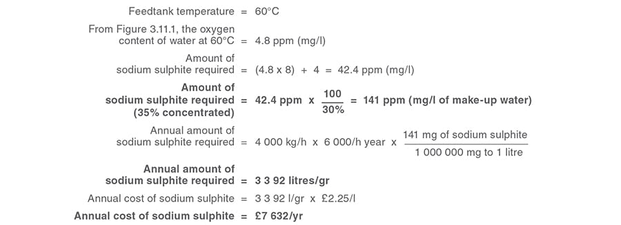
Example 3.11.1
Cost savings associated with reducing the dissolved oxygen in feedwater by heating.
Basis for calculation:
- The standard dosing rate for sodium sulphite is 8 ppm per 1 ppm of dissolved oxygen.
- It is usual to add an additional 4 ppm to maintain a reserve in the boiler.
- Typical liquid catalysed sodium sulphite contains only 45% sodium sulphite.
For the example

Calculation 1
Calculation 2
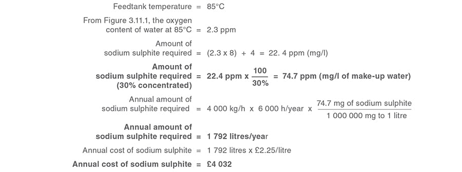
Annual cost saving

Obviously a cost is involved in heating the feedtank, but since the water temperature would be increased by the same amount inside the boiler, this is not additional energy, only the same energy used in a different place.
The only real loss is the extra heat lost from the feedtank itself. Provided the feedtank is properly insulated, this extra heat loss will be almost insignificant.
An important additional saving is reducing the amount of sodium sulphite added to the boiler feedwater. This will reduce the amount of bottom blowdown needed, and this saving will more than compensate for the small additional heat loss from the boiler feedtank.
To avoid damage to the boiler itself
The boiler undergoes thermal shock when cold water is introduced to the hot surfaces of the boiler wall and its tubes. Hotter feedwater means a lower temperature difference and less risk of thermal shock.
To maintain the designed output
The lower the boiler feedwater temperature, the more heat is required in the boiler to produce steam. It is important to maintain the feedtank temperature as high as possible, to maintain the required boiler output.
Cavitation of the boiler feedpump
Caution: very high condensate return rates (typically over 80%) may result in excessive feedwater temperature, and cavitation in the feedpump.
If water close to boiling point enters a pump, it is liable to flash to steam at the low pressure area at the eye of the pump impeller. If this happens, bubbles of steam are formed as the pressure drops below the water vapour. When the pressure rises again, these bubbles will collapse and water flows into the resulting cavity at a very high velocity.
This is known as ‘cavitation’; it is noisy and can seriously damage the pump.
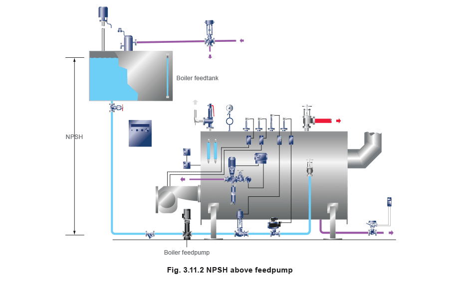
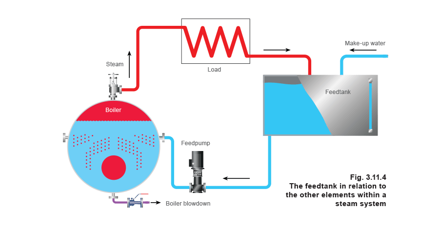
To avoid this problem, it is essential to provide the best possible Net Positive Suction Head (NPSH) to the pump so that the static pressure is as high as possible. This is greatly aided by locating the feedtank as high as possible above the boiler, and generously sizing the suction pipework to the feedpump (Figure 3.11.2).
Feedtank design
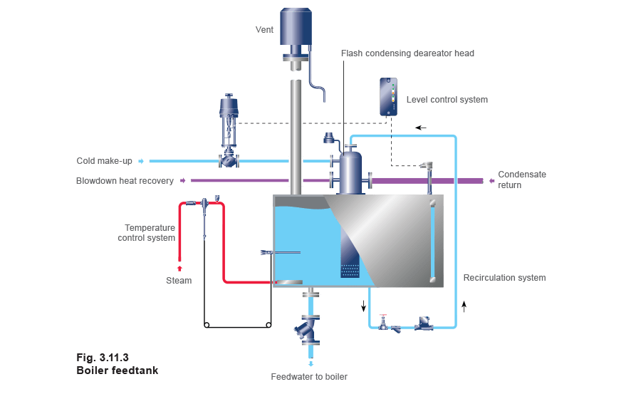
The feedtank (Figure 3.11.3) can influence the way in which the whole boiler house operates in several ways. By careful design of the feedtank and associated systems, substantial savings can be made in energy and water treatment chemicals together with increased reliability of operation.
Whilst cylindrical feedtanks, both vertical and horizontal, are not uncommon in other parts of the world, the rectangular shape is most regularly used in the UK. This normally offers the maximum volume of water storage for the floor area that it occupies.
Feedtank materials:
- Cast iron - Cast iron tanks are usually assembled from rectangular sections:
Problems often arise from leaks at the section joints, and they are prone to corrosion. - Carbon steel - Probably the most common construction material for feedtanks:
Uncoated, it is a relatively low cost material but it is extremely susceptible to corrosion. This weakness can be improved by applying suitable coatings to the surface, but the cost of this can be more than the cost of the tank, especially as the coating will also need regular maintenance. - Plastic - This material is not usually suitable for feedtanks due to the high cost of materials able to withstand the relatively high temperatures involved. However, plastic is a suitable material for the cold make-up water tank.
- Austenitic stainless steel - The enhanced life of a properly made feedtank in this material will invariably justify the higher initial cost. Type 304L is generally selected as the most appropriate grade of stainless steel.
Feedtank capacity
The feedtank provides a reserve of water to cover the interruption of make-up water supply. Traditional practice is to have a feedtank with sufficient capacity to allow one hour of steaming at maximum boiler evaporation. For larger plants this may be impractical and an alternative might be to have a smaller ‘hotwell’ feedtank with additional cold treated water storage. It should also have sufficient capacity above its normal working level to accommodate any surges in the rate of condensate return. This capacity is referred to as ‘ullage’.
A high condensate return rate can occur at start-up when condensate lying in the plant and pipework is suddenly returned to the tank, where it may be lost to drain through the overflow. If this occurs, it may be wise to review the condensate return system, to control the return rate and avoid wastage.
Feedtank construction
The following notes may be useful in designing a feedtank:
- Stiffening - The tank should be fully welded and it is very important to use adequate stiffening to strengthen the tank sides and top and to provide adequate support for the base. Failure to do so will result in excessive flexing and premature failure.
- Piping connections - All flanged piping connections should stand-off at least 150 mm to facilitate insulation. All screwed connections should stand-off by at least 20 mm.
- Lifting lugs - It is essential to fit lifting lugs to allow safe and easy installation.
Feedtank piping
Condensate return
As steam is generated, the water within the boiler evaporates and is replaced by pumping feedwater into the boiler.
As the steam passes around the system to the various items of steam-using plant, it changes state back to condensate, which is, essentially, very good quality hot water.
Unless some contamination is likely (perhaps due to the process), this condensate is ideal boiler feedwater. It makes economic sense, therefore, to return as much as possible for re-use. In reality, it is almost impossible to return all the condensate; some steam may have been injected directly into the process for applications such as humidification and steam injection, and there will usually be water losses from the boiler itself, for instance, via blowdown. Make-up (chemically treated) water will therefore have to be introduced to the system to maintain the correct working levels.
The return of condensate represents huge potential for energy savings in the boiler house. Condensate has a high heat content and approximately 1% less fuel is required for every 6°C temperature rise in the feedtank.
Figure 3.11.5(a) shows the formation of steam at 10 bar g when the boiler is supplied with cold feedwater at 10°C. The portion at the bottom of the diagram represents the enthalpy (42 kJ / kg) available in the feedwater. A further 740 kJ / kg of heat energy has to be added to the water in the boiler before saturation temperature at 10 bar g is reached.
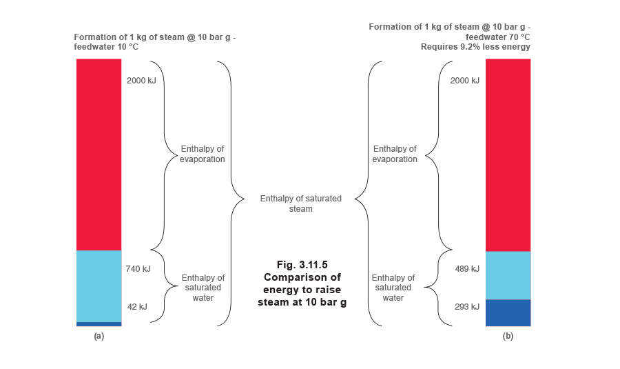
Figure 3.11.5(b) again shows the formation of steam at 10 bar g, but this time the boiler is fed with feedwater heated to 70°C by returning more condensate.
The increased enthalpy contained in the feedwater means that the boiler now only has to add 489 kJ/kg of heat energy to bring it up to saturation temperature at 10 bar g. This represents a saving of 9.2% in the energy needed to raise steam at this same pressure.
The returned condensate is virtually pure water and this saves not only on water costs but also on water treatment chemicals, which reduces the losses associated with blowdown.
If pressurised condensate is being returned then flash steam will be released in the feedtank. This flash steam needs to be condensed to ensure that both the heat and water content are recovered. The traditional method of doing this has been to introduce it into the feedtank through sparge pipes, but a more modern and effective method is to use a flash condensing deaerator head where cold make-up, condensate return and flash steam are mixed (see Figure 3.11.6).
Flash steam from heat recovery systems
A heat recovery system may, for example, recover flash steam from the boiler blowdown. It is another opportunity to use recovered heat to raise the feedtank temperature and so save fuel.
As with pressurised condensate, the flash steam needs to be condensed. Traditionally, this was achieved using sparge pipes, but a modern and much more effective method is the flash condensing deaerator head.
Make-up water
This is cold water from the water treatment plant that makes up any losses in the system.
Many water treatment plants need a substantial flow through them in order to achieve optimum performance. A ‘trickle’ flow as a result of a modulating control into the feedtank can, for example, have an adverse effect on the performance of a softener. For this reason a small plastic or galvanised steel cold make-up tank is often fitted. The flow from the softener is controlled ‘on / off’ into the make-up tank. From there a modulating valve controls its flow into the feedtank.
This type of installation leads to ‘smoother’ operation of the boiler plant. To avoid the relatively cold make-up water sinking directly to the bottom of the tank (where it will be drawn directly into the boiler feedwater line), and to ensure uniform temperature distribution, it is common practice to sparge the make-up water into the feedtank at a higher level.
Steam injection
As previously mentioned, there are significant advantages to maintaining the feedtank contents at a high temperature. One of the most convenient ways of achieving this higher temperature is by injecting steam into the feedtank.
Vent
The feedtank must be vented to prevent any build-up of pressure. As a guide, this vent will range in size from DN80 on a 2 000 litre tank to DN250 on a 30 000 litre tank. The vent should be fitted with a vent head, which incorporates an internal baffle to separate entrained water from the steam for discharge through a drain connection.
Overflow
This should be fitted with a ‘U’ tube water seal to prevent flash steam loss.
Feedpump take-off
If the take-off is from the base of the feedtank there should be a 50 mm internal stub to prevent any dirt in the bottom of the tank from entering the pipeline. It should be generously sized so that friction losses are minimised, and the net positive suction head (NPSH) to the feedpump is maximised.
Drain
A drain connection should be fitted in the bottom of the feedtank to facilitate its emptying for inspection.
Insulation
The feedtank should be adequately insulated to prevent heat losses. The advice of a reputable insulation specialist should be sought in selecting the correct material and economic thickness.
Inspection opening
An adequately sized inspection opening should be fitted to enable internal inspection and the fitting of ancillaries, as appropriate.
Water level control
Traditionally, float controls have been used for this application. Modern controls use level probes, which will give an output signal to modulate a control valve. Not only does this type of system require less maintenance but, with the use of an appropriate controller, a single probe may incorporate level alarms and remote indicating devices.
Level probes can be arranged to signal high water level, the normal working (or control) water level, and low water level. The signals from the probe can be linked to a control valve on the cold water make-up supply. The probe is fitted with a protection tube inside the feedtank to protect it from turbulence, which can result in false readings.
A local level indicator or water level gauge glass on the feedtank is recommended, allowing the viewing of the contents for confirmation purposes, and for commissioning level probes.
Temperature gauge
This can be a local or remote reading device.
Deaerators
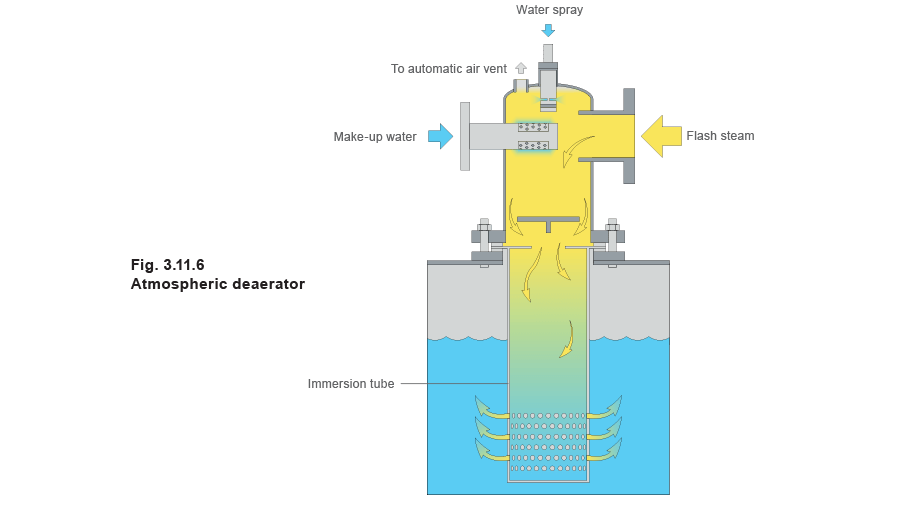
Atmospheric deaerator head
The mixing unit of a deaerator head brings together all the incoming flows. It mixes the high oxygen content cold make-up water with flash steam from the condensate and the blowdown heat recovery system. Oxygen and other gases are released from the cold water and can be automatically removed through a vent before the water enters the main feedtank.
The deareator head considerably reduces the amount of steam that would normally be expected to emanate from the tank under working conditions. Because of this, properly designed atmospheric deareator tanks fitted with deareator heads require less venting capacity than an ordinary tank fitted with a vented lid. Typically, vent sizes on an atmospheric deareator tank vary from DN80 on a 2000 L tank, to DN250 on a 30 000 L tank.
Pressurised deaerator
On larger boiler plants, pressurised deaerators are sometimes installed and live steam is used to bring the feedwater up to approximately 105°C to drive off the oxygen. Pressurised deaerators are usually thermally efficient and will reduce dissolved oxygen to very low levels.
Pressurised deaerators:
- Must be fitted with controls and safety devices.
- Are classified as pressure vessels, and will require periodic, formal inspection.
This means that pressurised deaerators are expensive, and are only justified in very large boiler houses. If a pressure deaerator is to be considered, its part load performance (or effective turndown) must be investigated.
A detailed review of pressurised deaerators is given in Module 21 of this Block.
Conditioning treatment
This is additional treatment which supplements external treatment, (for example, the base exchange system) and is generally carried out by adding chemicals in metered amounts, into either the feedwater tank or the feedwater pipeline prior to its entry into the boiler.
The chemical treatment required depends on many factors such as:
- The impurities inherent in the make-up water and its hardness.
- The volume of condensate returned for re-use and its quality in terms of pH value, TDS content, and hardness.
- The design of the boiler and its operating conditions.
Deciding on the type of chemical regime and water treatment system is a matter for a skilled water treatment specialist who should always be consulted.
The purpose of the conditioning treatment is to enhance the treatment of the raw water after it has been processed as far as possible by the main water treatment plant. It ensures quality because, inevitably, there will be some impurities that find a way through the main treatment system. The objectives of water treatment are:
- To prevent scale formation from low remaining levels of hardness which may have escaped treatment.
Sodium phosphate is normally used for this, and causes the hardness to precipitate to the bottom of the boiler where it can be blown down.
- To deal with any other specific impurities present.
These will be specific substances for specific applications.
- To maintain the correct chemical balance in the boiler water - to prevent corrosion it needs to be somewhat alkaline and not acidic.
Typically a 1% caustic solution will be used to achieve a target pH of between 9 and 11. British Standards BS 2486 recommends pH 10.5 - 12.0 for shell boilers @ 10 bar, pH 9 could be used in higher pressure boilers only.
- To condition any suspended matter.
This will be a flocculant or coagulant, which will cause the suspended matter to agglomerate and sink to the bottom of the boiler from where it can be blown down.
- To provide anti-foaming protection.
- To remove traces of dissolved gases.
These are primarily oxygen and carbon dioxide and the presence of these dissolved gases in the boiler plant and system will cause corrosion. It is, therefore, necessary to remove and / or neutralise them if damage is to be prevented.
Carbon dioxide
Dissolved carbon dioxide is often present in feedwater in the form of carbonic acid and this causes the pH level to fall. Proper pH control will correct this but carbon dioxide is also released in boilers due to heating of carbonates and bicarbonates. These decompose into caustic soda with the release of carbon dioxide. This may need to be dealt with by use of a condensate corrosion inhibitor, to prevent corrosive attack to the condensate system.
Oxygen
The most harmful of the dissolved gases is oxygen, which can cause pitting of metal. Very small amounts of oxygen can cause severe damage. It can be removed both mechanically and chemically. The amount of dissolved oxygen present is dependent on the temperature of the feedwater; the lower the feedwater temperature, the larger the volume of dissolved oxygen present.
Any remaining oxygen is then dealt with by the addition of a chemical oxygen scavenger such as catalysed sodium sulphite.
8 ppm of sodium sulphite is sufficient to deal with 1 ppm of dissolved oxygen. However, it is usual to add an extra (or ‘reserve’) of 4 ppm of sodium sulphite because:
- There is a significant danger of corrosive damage.
- The chemical dosing system is usually ‘open loop’ with water samples taken at intervals, and adjustments made to the dosing rate.
- There is a concern about complete dispersion of the chemical, perhaps due to the method of injection, circulation currents, or stratification within the feedtank.
The total dosing rate, therefore, is 8 ppm of sodium sulphite per 1 ppm of dissolved oxygen plus 4 ppm.
Other oxygen scavengers involve organic compounds or hydrazine. The latter, however, is thought to be carcinogenic, and is not generally used in low and medium pressure plants.
Other ‘internal treatment’ to provide protection for the boiler and the condensate system can include:
- Neutralising amines - These have a neutralising effect on the acid generated by the solution of carbon dioxide in condensate.
- Filming amines - These create an oil attractive, water repellent film on metal surfaces which is resistant to both carbon dioxide and oxygen.
Further detail on this complicated subject is available from water treatment handbooks and water treatment specialists; this is very much a matter for expert advice and professional analysis.
There are however, one or two areas which call for further explanation:
- The main boiler water treatment programme is aimed at changing scale-forming salts into soft or mobile sludges. The sludge conditioners used in the chemical dosing prevent these solids from depositing on metal surfaces and keep them in suspension.
- Under high pressures and temperatures, silica can present a real problem because it can combine with the metal heating surfaces to cause hot spots. Special synthetic polymers can prevent this problem.
- Alkalinity levels in the boiler are particularly important and these are controlled by the addition of sodium hydroxide.
Maintaining a pH level of between 10.5 - 12 will avoid corrosion problems by providing stable conditions for the formation of a film of magnetite (Fe3O4) in a thin, dense layer on the metal surfaces, protecting them from corrosive attack.
Chemicals added during the conditioning treatment will increase the TDS level in the boiler water and a higher rate of blowdown will be required.