The Boiler House

Contents
Steam Accumulators
A complete overview of the need for steam storage to meet peak load demands in specific industries, including the design, construction and operation of a steam accumulator, with calculations.
The purpose of a steam accumulator is to release steam when the demand is greater than the boiler’s ability to supply at that time, and to accept steam when demand is low.
Steam accumulators are sometimes thought of as relics of the ‘steam age’ with little application in modern industry.
The following Sections within this Module will:
Boiler design
Contemporary boilers are significantly smaller than their counterparts of only 30 years ago. This reduction in boiler size has been brought about by users, who demand that boilers be:
- More efficient in terms of fuel input to steam output.
- More responsive to changes in demand.
- Smaller, and so take up less floor space.
- Cheaper to buy and install.
These targets have been met in part by today’s more sophisticated controls/burners which respond faster and more accurately to changes in demand than those of bygone years. However, a boiler’s response to changes in demand is also affected by the laws of nature, for example: how much water is to be heated and the heat transfer area available to transfer that heat from the burner flame to the water.
Response times have been improved by physically reducing the external dimensions of the boiler for any given output, and by cramming the insides full of tubes to increase the heat transfer area. This means that the modern boiler holds less water, and the heat transfer area per kg of water is greater. Consider the situation of today:
- Steam demand from the plant is increased, and the pressure in the boiler falls to the burner control set point.
- The burner control purges the combustion chamber, and the burner is ignited.
- The large heat transfer area and the lower mass of water combine to rapidly evaporate the water in the boiler to satisfy the demand for steam.
As covered in Module 3.7, ‘Boiler Fittings and Mountings’, the energy stored in a boiler is contained in the water which is held at saturation temperature. The greater the amount of water inside a boiler, the greater the amount of stored energy to cope with changes in demand/load.
Table 3.22.1 compares an old Lancashire boiler of the 1950s with a modern packaged boiler. Note that the modern packaged boiler contains only 20% of the water held in a similarly rated Lancashire boiler. It follows from this that the reserve of energy held in the modern packaged boiler is only 20% of the Lancashire boiler. This suggests that the modern packaged boiler cannot cope with peak demands in the way an old Lancashire boiler could.
Also note from Table 3.22.1, that the ‘steam release rate’ from the surface of the water inside the modern packaged boiler has increased by a factor of 2.7. This means that the steam has only 1/2.7 (40%) of the time available in a Lancashire boiler to separate itself from the water. At times of peak demand this may mean that wet steam is being exported from the modern packaged boiler, and possibly at a lower pressure than that which it was designed to operate - Covered in Module 3.12 ‘Controlling TDS in the Boiler Water’.
Water which is carried over with the steam will be dirty (approximately 3 000 ppm TDS), and will contaminate control valves and heat transfer surfaces. It may even block some of the smaller orifices in pressure sensing devices, steam traps and so on.
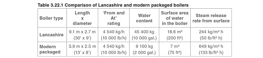
Note: The information to create Table 3.22.1 was supplied by Thermsave. Imperial units are also shown in the Table to provide an insight into the factors applied in the designing of boilers in the past.
Peak demands
Steam demands on any process plant are rarely steady, but the size and type of the fluctuations depend on the application and the industry. Peaks may occur once a week or even once a day during start-up.
The biggest problems caused by peak demands are usually associated with batch processing industries:
- Brewing.
- Textiles.
- Dry-cleaning.
- Canning.
- Lightweight concrete block manufacturers.
- Specialised areas of the steel making industry.
- Rubber industries with large autoclaves.
For these processes the peaks may be heavy and long-term, and measured in fractions of an hour.
Alternatively, load cycles can consist of short-term frequent peaks of short duration but very high instantaneous flowrate:
- Hosiery finishing.
- Rubber.
- Plastic and polystyrene moulding.
- Steam peeling.
- Hospital and industrial sterilisation.
Figure 3.22.1, shows that in each case the demands are almost instantaneous and the peaks are well above the average load. The result of a sudden demand on boiler plant is a pressure drop in the boiler, because the boiler and its associated combustion equipment are unable to generate steam at the rate at which it is being drawn off.

Peak demands and subsequent pressure drops may have quite serious consequences on factory production.
At worst, the result is a boiler ‘lockout’, due to the elevation of water level caused by rapid boiling, followed by its collapse. This is seen as a low water level alarm by the level controls.
At best, the steam produced is wet and contaminated. This, coupled with a reduction in pressure, can lead to:
- Increased process times.
- A reduction in product quality or even damage or loss of the product.
- Waterhammer in the steam mains causing distress to pipework and fittings, and possible danger to personnel.
For the boiler plant, peak demands are responsible for:
- A higher level of maintenance.
- Reduced boiler life.
- Reduced fuel efficiency.
This is because the combustion equipment is continually cycling from low to high fire, and even shutting off during periods of very low demand, only to fire again a few minutes later, with all the pre and post-purge chilling effects.
Multiple or oversized boilers may be used in an effort to cope with peak demands (and the subsequent dips in demand) which inevitably result in low efficiencies.
To illustrate this point, it can be assumed that:
- For an average steam boiler, less than 1% of the losses are due to heat radiated from the boiler shell (for example: 1% of the Maximum Continuous Rating (MCR) of the boiler).
- If a boiler is then producing 50% of its MCR, the losses due to radiation are 2% relative to its production rate.
- If a boiler is producing 25% of its MCR the losses are 4% of its production rate.
And so on, until a boiler is simply maintained at a pressure without exporting any steam to the factory. At this point, 1% of its MCR is a 100% loss relative to its steam production rate.
If boiler plant is sized for peak loads, problems arise due to oversizing relative to the average demand. In practice, a boiler may shut off during a period of low demand. If this is then followed by a sudden surge of demand and the boiler is not firing, an alarm situation may arise.
Alarms will ring, the boiler may lockout and steam recovery will be slow and arduous.
In short, peaks are responsible for:
- Loss of production.
- Reduced product quality.
- Increased production times.
- Poor quality steam from the boiler.
- Low fuel efficiency.
- High maintenance costs.
- Reduced boiler life.
Load levelling techniques
Modern boilers are very efficient when properly loaded and respond quickly to load increases, provided that the boiler is firing. However, conventional shell boilers are generally unable to meet large peak demands in a satisfactory way and should be protected from large fluctuating loads.
Various methods are used in an attempt to create a stable load pattern to protect the boiler plant from the effects of large fluctuating loads.
Engineering methods:
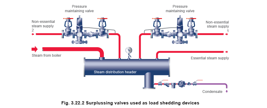
Pressure maintaining valves (also called surplussing valves) can be used as load shedding devices by isolating non-essential parts of the plant and thereby giving priority to essential plant, a typical arrangement is shown in Figure 3.22.2. The success of this method again depends on the severity of the peaks and the assumption that the boiler is firing when the peak develops.
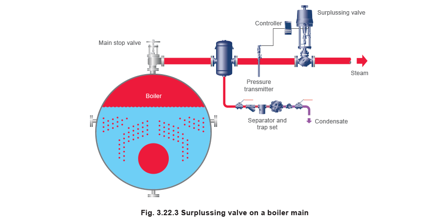
Surplussing valves can also be fitted directly to the boiler or on the steam main to the factory, as shown in Figure 3.22.3.
The set pressure should be:
- Less than the ‘high fire’ control pressure, to prevent any interference of the surplussing control with the burner controls.
- High enough to maintain the pressure in the boiler at a safe level.
In terms of sizing the surplussing valve, the requirement is for minimum pressure drop. As a general indication, a line size valve should be considered.
Two-element or three-element water level control. These can be successful as long as the peaks are not violent and the boiler is firing when the peak develops; the boiler must also have sufficient capacity.
Two-element control uses inputs from the boiler water level controls and the steam flowrate to position the feedwater control valve.
Three-element control uses the above two elements plus an input from a feedwater flow measuring device to control the incoming feedwater flowrate, rather than just the position of the feedwater control valve. (This third element is only appropriate on boilers which use modulating level control in boiler houses with a feedwater ring main.)
Example 3.22.1
A boiler is rated at 5 000 kg/h ‘From and At’
The high/low fire pressure settings are 11.3/12.0 bar g respectively (12.3/13.0 bar a).
The surplussing valve setting is 11.0 bar g (12.0 bar a).
- Based on a velocity of approximately 25 m/s, a 100 mm steam main would be selected.
- Kvs of a standard DN100 surplussing control valve is 160 m³/h
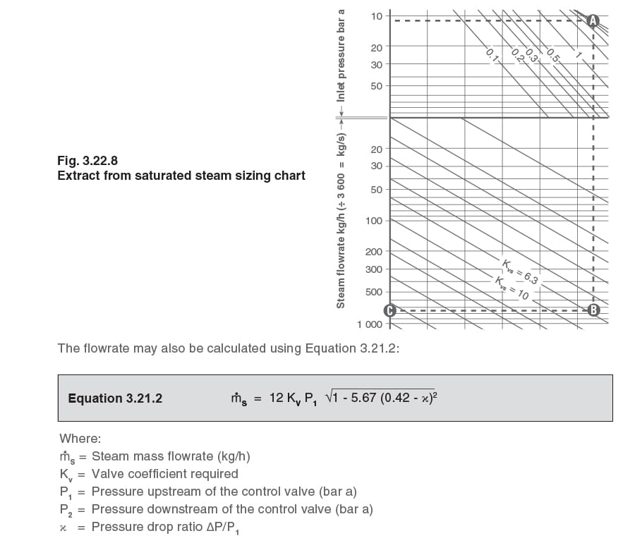
- Using the following mass flow equation for saturated steam the pressure downstream of the surplussing valve (P2) can be calculated:
In this example, at low fire, the boiler pressure is given as 12 bar g (13 bar a).
It can be calculated from Equation 3.21.2 that the pressure after the fully open surplussing valve is 11.89 bar g (12.89 bar a).
Consequently, the pressure drop is small (0.11 bar) and would not be significant in normal operation. However, if the pressure should fall to 11.0 bar g, the surplussing valve will start to close in order to maintain upstream pressure.
The proportional band on the controller should be set as narrow as possible without making the valve ‘hunt’ about the set point.
Both methods of applying pressure-maintaining valves may provide protection to the boiler plant, but they will not overcome the fundamental requirement of more steam for the process.
Management methods
These include, for example, staggered starts on processes to keep peak loads as low as possible. This method of smoothing out peaks can be beneficial to the boiler plant but may be detrimental and restrictive to production, having much the same effect as the pressure-maintaining valve.
It is, however, impossible to smooth out short-term peaks using only management methods.
In a factory where there are many individual processes imposing such peaks it is possible for this to have a levelling effect on the load, but equally so, it is also possible for the many individual processes to peak simultaneously, with disastrous effects.
If the above methods do not provide the required stability of demand, it may be time to consider a means of storing steam.
The steam accumulator
The most appropriate means of providing clean dry steam instantaneously, to meet a peak demand is to use a method of storing steam so that it can be ‘released’ when required. Storing steam as a gas under pressure is not practical due to the enormous storage volume required at normal boiler pressures.
This is best explained in an example:
In the example used later in this Module, a vessel with a volume of 52.4 m³ is used.
- Charging pressure is 10 bar g (specific volume = 0.177 m³/kg).
- Discharge pressure is 5 bar g (specific volume = 0.315 m³/kg).
Based on these parameters, the resultant energy stored and ready for instant release to the plant is contained in 130 kg of steam. This amounts to only 5.2% of the energy stored and ready for use, compared to a water filled accumulator.
In practice there are two ways of generating steam:
- By adding heat to boiling water, indirectly via a combustion tube and burner, as in a conventional boiler.
- By reducing the pressure on water stored at its saturation temperature. This results in an excess of energy in the water, which causes a proportion of the water to change into steam.
This phenomenon is known as ‘flashing’, and the equipment used to store the pressurised water is called a steam accumulator. There are, in principle, two types of systems available for steam storage; the pressure-drop accumulator and the constant pressure accumulator. This module only considers the former type.
A steam accumulator is, essentially, an extension of the energy storage capacity of the boiler(s). When steam demand from the plant is low, and the boiler is capable of generating more steam than is required, the surplus steam is injected into a mass of water stored under pressure. Over a period of time the stored water content will increase in temperature and pressure until it finally achieves the saturation temperature for the pressure at which the boiler is operating.
Demand will exceed the capability of the boiler when:
- A load is applied faster than the boiler’s ability to respond - for example, the burner(s) may be extinguished and a purging cycle must be completed before the burner can be safely ignited. This may take up to 5 minutes, and rather than adding heat to the boiler, the purging cycle will actually have a slight cooling effect on the water in the boiler. Add to this the fact that the flashing of the boiler water will cause a drop in water level, and the boiler level control system will automatically compensate for this by bringing feedwater in at, for example, 90°C. This will have a quenching effect on the water already at saturation temperature, and will aggravate the situation.
- A heavy demand occurs over a longer than normal period.
In either case, the result is a drop in pressure inside the steam accumulator, and as a result of this some of the hot water will flash to steam. The rate at which the water flashes to steam is a function of the storage pressure, and the rate at which steam is required by the system being supplied.
Charging
The pressure-drop steam accumulator consists of a cylindrical pressure vessel partially filled with water, at a point between 50% and 90% full depending on the application. Steam is charged beneath the surface of the water by a distribution manifold, which is fitted with a series of steam injectors, until the entire water content is at the required pressure and temperature.
It is natural that the water level will rise and fall during charging and discharging.
If the steam accumulator is charged using saturated (or wet) steam, there may be a small gain in water due to the radiation losses from the vessel. Normally, a slightly greater mass of steam is discharged than is admitted.
A steam trap (ball float type) is fitted at the working level and acts as a level-limiter, discharging the small amount of surplus water to the condensate return system.
However, if the steam accumulator were charged using superheated steam, or if the radiation losses are very small, there would be a gradual loss of water due to evaporation, and a feedvalve or pump, under the control of level probes, would be required to make up the deficit.
Discharging
As a pressure drop occurs in a steam accumulator with the stored water at saturation temperature, flash steam will be generated at the rate demanded by any load above the boiler capacity; consequently the overload condition will be satisfied. When the overload is followed by a demand below the boiler capacity the steam accumulator is charged using surplus steam from the boiler. This charge and discharge cycle explains the name ‘steam accumulator’ and continually allows the boiler to fire up to its maximum continuous rating.
The charging/discharging cycle
The accumulator needs to be fully charged at the beginning of its discharge period, for it to operate correctly. To allow this, two main events must be satisfied:
- Enough time must be available from the end of one overload period to the beginning of the next, to recharge the water stored in the accumulator.
- The average off-load steam demand must be lower than the boiler capacity (the maximum continuous rating or MCR), such that sufficient surplus boiler capacity is available to recharge the water stored in the accumulator during off-peak times.
Other criteria are also important to ensure the accumulator has enough capacity, and these must be satisfied by the design:
- Enough water must be stored to provide the required amount of flash steam during the discharge period. This can be satisfied by ensuring the accumulator volume is large enough.
- Higher steam release rates will produce wet steam. The velocity and flowrate at which the flash steam is released from the water surface must be below a predetermined value. This can be satisfied by ensuring the water surface area is large enough which, in turn, depends on the accumulator size.
- The evaporation capacity must be sufficient. This depends on the pressure at which the water is stored when fully charged (the boiler pressure) and the minimum pressure at which the accumulator will operate at the end of the discharge period (the accumulator design pressure). The larger the differential between these two pressures, the more flash steam will be produced.
- The accumulator design pressure must be higher than the downstream distribution pressure. This is necessary to create a pressure differential across the downstream pressure reducing valve (PRV), to allow the required flow from the accumulator to the plant. The closer the accumulator pressure to the distribution pressure, the smaller the accumulator but this also gives a smaller pressure differential across the PRV. This requires a larger PRV; large enough to pass the highest overload demand when the accumulator is at its design pressure (the minimum pressure in the accumulator at the end of the discharging period).
Sizing a steam accumulator
A steam accumulator in the steam system gives increased storage capacity. Proper design of the steam accumulator ensures that any flowrate can be catered for. There are no theoretical limits to the size of a steam accumulator, but of course practical considerations will impose restrictions.
In practice the steam accumulator volume is based on the storage required to meet a peak demand, with an allowable pressure drop, whilst still supplying clean dry steam at a suitable steam release velocity from the water surface. Example 3.22.2 below, is used to calculate the potential of steam capacity in a horizontal steam accumulator.
Example 3.22.2
Boiler:
Maximum continuous rating = 5 000 kg/h
Normal working pressure = 10 bar g (hf = 781 kJ/kg, from steam tables)
Burner switching differential = 1 bar (0.5 bar either side of 10 bar g)
Plant requirements:
Maximum instantaneous overload = 12 000 kg/h
Distribution pressure = 5 bar g
Although the maximum instantaneous overload is 12 000 kg/h, the mean value of the overload should be used to size the accumulator.
This prevents unnecessary oversizing of the accumulator. Equally, it is necessary to determine and use the mean ‘off-peak’ load in the sizing calculation. Off-peak load is any load below the boiler MCR.
Finding the mean value of the overload and off-peak load
There are three possible methods to establish the mean loads for existing boiler plant:
- To guestimate, based on experience.
- To interrogate the existing boiler steam output charts to establish the mean loads and the time periods over which they occur.
- To program a steam meter’s computer to integrate the steam load over both the overload and off-peak load periods.
Method 1 could prove to be rather reckless, if an expensive accumulator ended up too small.
However, if the boiler plant is still at the design stage, an educated guess will be the only option. From the designer’s knowledge of the installation, it should be possible to give a reasonable estimate of the maximum plant load, the load diversity, and the times over which they occur.
Method 2 is quite easy to expedite, and should give a reasonably accurate result.
Method 3 would provide the most accurate results, and the cost of the steam meter is small relative to the overall cost of an accumulator project.
The following procedure shows how to determine the mean steam loads from an existing chart recording the load pattern. The procedure is built up from Figure 3.22.4, which shows the flow pattern for Example 3.22.2.

From Figure 3.22.4, it can be seen that the off-peak loads have been divided up into the following mean loads and time periods. From this data, the mean surplus load for each off-peak period can be determined.
The mean surplus flow is calculated in the following way:

1st off-peak load
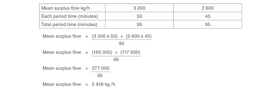
2nd off-peak load
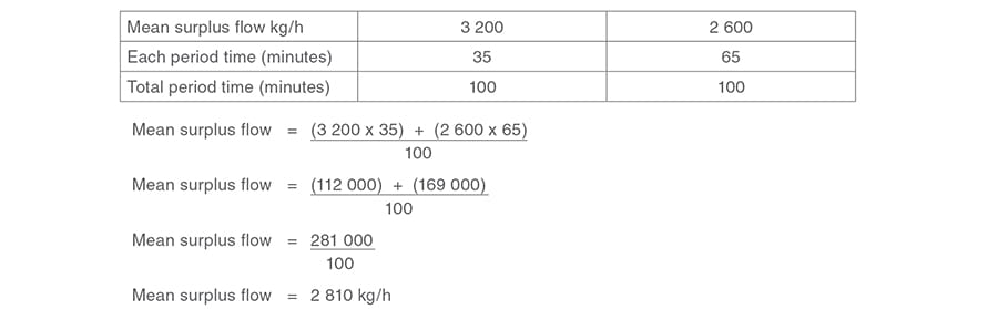
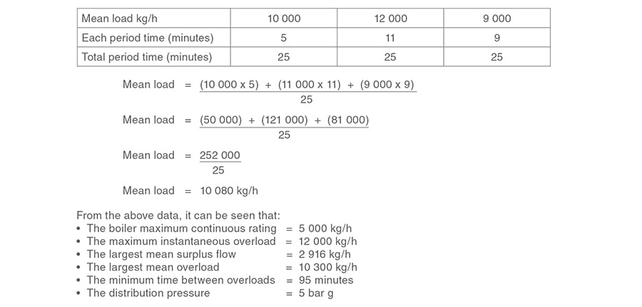
A similar exercise is carried out for the overload periods from Figure 3.22.4.
1st overload
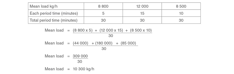
2nd overload
The accumulator design pressure needs to be chosen, and it is usual to choose a pressure 1 bar higher than the distribution pressure. This gives a reasonable flash steam capacity, without unduly oversizing the downstream PRV.
In this example the distribution pressure is 5 bar g, so the accumulator design pressure can initially be considered at 6 bar g (Note: the water mass is taken at boiler working pressure).
From this information, an accumulator may now be sized.
Steam accumulator:
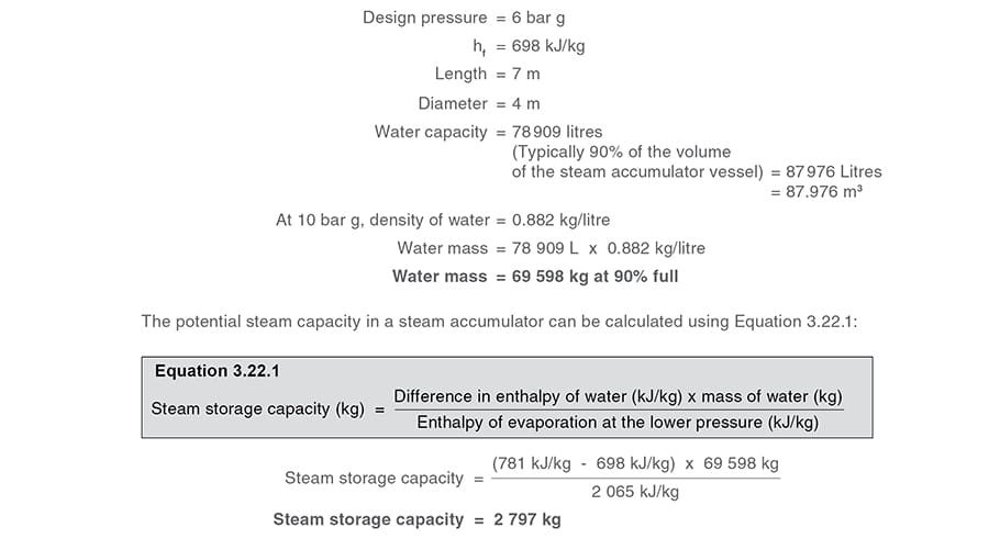
Note that this 2 797 kg of flash steam will be released in the time taken for the pressure to drop. If this has been an hour, the steaming rate is 2 797 kg/h; if it were over 30 minutes, then the steaming rate would be:

If the steam accumulator is connected to a boiler rated at 5 000 kg/h, and supplying an average demand within its capacity, the combined boiler and accumulator outputs could meet average overload conditions of 5 594 + 5 000 = 10 594 kg/h for 30 minutes. The alternative is an additional combination of boilers capable of generating 10 594 kg/h for 30 minutes with the limitations previously noted.
It is now possible to check the accumulator size.
The figures as used in Example 3.22.2 are used below to facilitate checking.
Boiler
Maximum continuous rating = 5 000 kg/h
Normal working pressure = 10 bar g
Plant requirements
Largest mean overload = 10 300 kg/h for 30 minutes every 95 minutes
Pressure = 5 bar g
Required steam storage = 10 300 kg/h - 5 000 kg/h steam supplied by the boiler
Required steam storage = 5 300 kg/h
However, steam is only required for 30 minutes every hour, so the steam storage required must be:

The amount of water required to release 2 650 kg of steam is a function of the proportion of flash steam released due to the drop in pressure.
This satifies the criterion of having enough water to produce the required amount of flash steam. It can be seen that the storage capacity of 2 797 kg is greater than the storage required of 2 650 kg of steam.
If the steam accumulator will be charged at 10 bar g by the boiler, and discharged at 6 bar g to the plant, the proportion of flash steam can be calculated as follows:
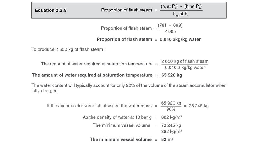
The vessel capacity is larger at 87.9 m³, so the vessel satisfies this criterion.
Using the vessel dimensions given earlier, the water surface area is approximately 20.53 m² when fully charged, at a volume of 90% of the vessel capacity.
The maximum steaming rate from the accumulator is given as 5 300 kg/h, therefore:

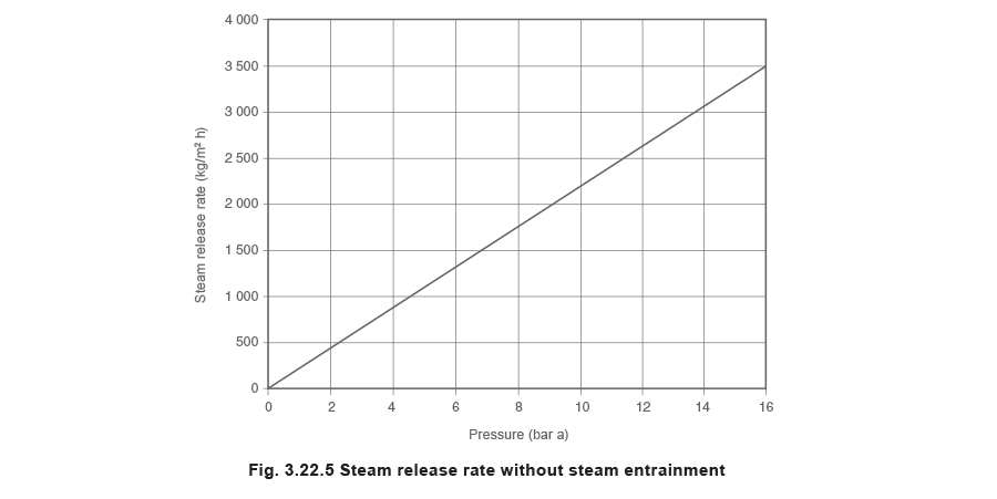
Empirical test work shows that the rate at which dry steam can be released from the surface of water is a function of pressure. A working approximation suggests:
Maximum release rate without steam entrainment (kg/m² h) = 220 x pressure (bar a)
The steam accumulator in Example 3.22.2 is operating at 6 bar g (7 bar a). The maximum release rate without steam entrainment will be:
220 x 7 bar a = 1 540 kg/m² h
This is shown graphically in Figure 3.22.5.
The example at 258 kg/m² h is well below the maximum value, and dry steam can be expected. Had the steam release rate been too high, different diameters and lengths giving the same vessel volume would need to be considered.
It must be emphasised that this is only an indication, and design details should always be delegated to specialist manufacturers.
Steam accumulator controls and fittings
The following is a review of the equipment required for a steam accumulator installation, together with some guidance on sizing and selection of appropriate equipment.
Using figures from Example 3.22.2:
Boiler:
Maximum continuous rating = 5 000 kg/h
Normal working pressure = 10 bar g
Accumulator:
Mass of water required for steam storage = 65 920 kg (fully charged and 90% of vessel volume)
P1 (boiler pressure) = 10 bar g (fully charged)
P2 (discharge pressure) = 6 bar g (fully discharged)
Plant requirements:
Pressure = 5 bar g
Largest mean overload = 10 300 kg/h for 30 minutes every 95 minutes, of which, 5 000 kg/h is supplied by the boiler.
From these figures it can be deduced that 65 920 kg of water must be heated from saturation temperature at 6 bar g to saturation temperature at 10 bar g in 95 minutes.
Pipework
The pipework between the boiler and the steam accumulator should be sized, as per normal practice, on a steam velocity of 25 to 30 m/s and the maximum output of the boiler.
In the case of Example 3.22.2, this would require a DN100 pipeline from the boiler to the accumulator, to carry the boiler Maximum Continuous Rating (MCR) of 5 000 kg/h @ 10 bar g.
The pipework from the accumulator to the downstream PRV should be sized on the maximum instantaneous overload and a velocity of no more than 20 m/s. This would require a DN250 nominal bore pipe for this example, with an accumulator design pressure of 6 bar g.
Stop valve
A line-size stop valve is required in addition to the boiler crown valve. A suitably rated stop valve, preferably in cast steel, would be appropriate.
Check or non-return valve
A line-size check valve is required to prevent reverse flow of the steam back to the boiler in the event of the boiler being deliberately shut down, or perhaps, the boiler locking-out.
A disc check valve would be an appropriate choice.
Surplussing valve
The surplussing valve is essential to ensure that the rate at which steam is flowing from the boiler to the accumulator is within the capability of the boiler. Example 3.22.1, shows how the valve would be sized.
Pilot operated, self-acting surplussing valves may be used in smaller installations, provided the narrow (and non-adjustable) proportional band is acceptable. A pneumatic controller and control valve is more appropriate to larger installations, and offers the advantage of an adjustable proportional band.
For this application a DN100 pneumatically operated control valve with appropriate operating and shut-off capability, would be selected.
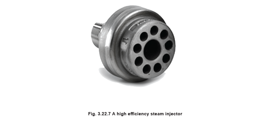
Steam injection equipment
A properly sized steam inlet pipe must feed to well below the water surface level and into a steam distribution header/manifold system such as shown in Figure 3.22.6.
The steam is injected into the water.
It is important to remember that the injector capacity will reduce as the pressure in the vessel increases, as the differential pressure between the injected steam and the vessel pressure is reduced.
At very low flowrates the steam will tend to issue from the injectors closest to the steam inlet pipe(s).
The design of the inlet pipe(s) and the manifold system, together with the placement of the injectors, must provide even injection of steam throughout the length of the accumulator regardless of actual steam flowrate.
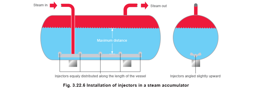
The discharge from the injectors will be very hot water and steam, possibly with some condensing steam bubbles, at very high velocity, promoting turbulence and mixing in the water mass. They should not discharge directly against, or close to, the walls of the vessel. Angled installation may therefore be advisable. Ideally, they should also be angled in different directions to assist with more even distribution.
A nominal arrangement is shown in Figure 3.22.6.
In very long vessels, more regular distribution may be achieved if two or more inlet pipes are used. In such cases, it is very important that the inlet pipes are carefully manifolded together from the supply main.
All the injectors should be installed as low down in the accumulator as possible to ensure the maximum possible liquid head above them. It may also be appropriate to install the injectors at a slight angle to avoid erosion of the vessel.

Manufacturers’ sizing tables will give the Kvs value of steam injectors (see Table 3.22.2)
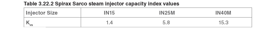
Using the data from Table 3.22.2 and referring to Figure 3.22.8, an extract from the saturated steam sizing chart Figure 3.22.9:
- Draw a line horizontally to the right across from the ‘x’ axis at 11 bar a (10 bar g) until it intersects the critical pressure drop line, point (A).
- Draw a line vertically down the chart from point (A) until it intersects the Kvs value of the injector, point (B), (For example Kvs 5.8 for an IM25M injector).
- Draw a line horizontally to the left, until it intersects the ‘y’ axis, point (C). The value shown will be the capacity of the injector.
(Approximately 760 kg/h for this example).
Sizing and quantifying the injectors
The above exercise gives a capacity of 760 kg/h for one injector; but this only relates to the start of the charging period, when the vessel pressure is at its lowest, and the injector capacity is at its highest.
It must be remembered that, as more steam is injected into the vessel, the vessel pressure will rise, effectively reducing the injectors’ capacities, until the vessel pressure may eventually equalise with the boiler pressure, and no flow can take place.
Because of this, it is not practical to use the one (highest) flowrate, 760 kg/h in this example.
Instead, it is necessary to find the mean injection rate over the charging period.
This can be done by using Equation 3.21.2 to calculate the flow at different vessel pressures.
In this example, the vessel pressure will vary between 6 bar g and 10 bar g. The greater the number of pressures taken, the greater the accuracy but, in general, taking increments at 10% of the difference between boiler and accumulation pressure will give a reliable mean value. Table 3.22.3 shows the calculations for an IN25 injector (1") with a Kv of 5.8.

The total flow of 6 076 kg/h is divided by the number of entries. it must be remembered to include the zero entry as well; hence there are eleven entries to consider.

It can be seen that the mean flowrate of 553 kg/h is somewhat less than the maximum capacity of 759 kg/h. If the maximum capacity were used to quantify the number of injectors, then not enough injectors would be chosen.
The number of injectors required can be determined by dividing the steam flow by the amount a single injector can supply.

Note: A number of smaller injectors would be preferable to one large injector to ensure proper mixing within the steam accumulator.
This sizing chart is empirical and should not be used for critical applications

Calculating the time required to recharge the vessel
From the load patterns shown in Figure 3.22.4, it has been shown that the minimum time between charge cycles is 95 minutes. It is now necessary to check that the vessel can be recharged in less time than this.
It has been shown that the quantity of steam used during the discharge period is 2 650 kg.
The mean surplus flow of steam available during the recharging period has been calculated from Figure 3.22.4 as 2 916 kg/h.
The time required for recharging is proportional to the ratio of the mass of steam used during discharge to the rate of surplus steam flowing in the off-peak period:

As the required recharging time is less than the time between the shortest overload cycle of 95 minutes, the balance between the overload time and the recharging time can be satisfied by the accumulator.
Therefore, the accumulator size of 7 metres long by 4 metres diameter provides sufficient capacity for this particular example.
Pressure gauge
A suitably ranged pressure gauge is required to show the pressure within the steam accumulator.
Ideally it should be marked to show:
- Minimum pressure (plant steam pressure).
- Maximum pressure (boiler steam pressure).
- Vessel maximum working pressure.
Safety valve
If the maximum working pressure of the accumulator is equal to, or greater than that of the boiler, then a safety valve(s) may not be required.
However, the user may be concerned about other less obvious scenarios. For example, in the event of a plant fire, if the accumulator were fully charged and all the inlets and outlets were closed, the pressure in the accumulator could rise. A discussion with the insurance inspector would be essential before a decision is made.
As with all safety valve installations, the discharge should be to a safe area through an adequately sized vent pipe, which is properly drained.
Air vent and vacuum breaker
When the steam accumulator starts from cold, the steam space is full of air. This air has no heat value, in fact it will adversely affect the steam plant performance (as demonstrated in Dalton’s Law) and also have the effect of blanketing heat exchange surfaces. The air will also give rise to corrosion in the condensate system.
The air may be purged using a simple cock, normally left open until the steam accumulator is pressurised to about 0.5 bar. An alternative to the cock is a balanced pressure air vent, which not only relieves the boiler plant operator of the task of manually purging air (and hence ensuring that it is actually done), but is also more dependable in purging any other gases which accumulate in the vessel during use.
Conversely, when the steam accumulator is taken off line, the steam in the steam space condenses and leaves a vacuum. This vacuum causes pressure to be exerted on the vessel from the outside, and can result in air leaking in through the inspection doors. A vacuum breaker will avoid this situation.
Drain cock
This valve would be used to drain the vessel for maintenance and inspection work.
A DN40 valve would be suitable for the size of the accumulator in Example 3.22.2.
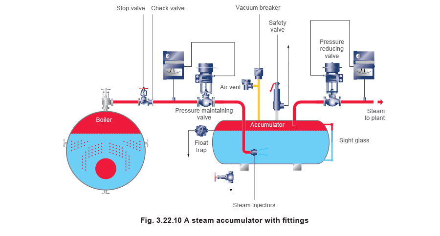
Overflow
A ball float trap with integral thermostatic air vent must be fitted as in Figure 3.22.10. When installed as shown, the water level inside the accumulator will not rise above this point because the trap will operate as an automatic overflow valve. When the water level drops, that is, when steam is drawn off at a faster rate than it is replaced, the trap will automatically close to prevent the escape of steam.
The use of a float trap with an integral thermostatic capsule as a level limiting device, offers the additional advantage of air venting.
The trap should be installed near to the gauge glass. The discharge from the trap should be directed back to the boiler feedtank, taking care to avoid excessive backpressure or lift.
The size of float/thermostatic trap will vary according to the size of the accumulator, and would typically be size DN32 or DN40 for Example 3.22.2.
Water level gauge
The variation in level within the steam accumulator will not be great because only 5% (approximately) of the mass of water will flash to steam, however, some means of viewing the water level is essential. Clearly the gauge should be rated to operate at the steam accumulator maximum working pressure. However, from a stock holding and plant standardisation point of view, there is some merit in using a gauge the same as the boiler.
Only a single gauge glass is required.
Pressure reducing station
A pressure reducing station is fitted to the discharge. As the pressure reducing valve opens to maintain the downstream pressure, a reduction in pressure occurs in the steam accumulator causing some of the water to flash to steam.
The pressure reducing valve should be sized on the following data:
P1 = Accumulator pressure (6 bar g on example)
P2 = Plant pressure (5 bar g on example)
ΔP = 6 - 5 = 1 bar
Flowrate = Maximum overload flowrate (12 000 kg/h on example)
An appropriate valve can now be selected either from the manufacturer’s sizing charts or using the saturated steam sizing chart shown in Figure 3.22.9.
For sizes up to DN80, a pilot operated self-acting valve would be suitable, whilst a pneumatically actuated control valve is appropriate on larger sizes.
Pipework
It is appropriate at this point to check that the pipework between the steam accumulator pressure reducing station and the plant is adequately sized. This pipe should be sized as per normal practice on a steam velocity of 25 to 30 m/s, but using the peak flowrate from the steam accumulator at the plant pressure, in this instance 5 bar g.
Typical arrangements of steam accumulators:
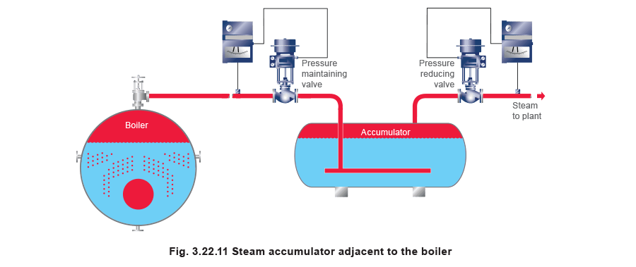
Figure 3.22.11 shows all the steam generated by the boiler plant passing through the steam accumulator. This is the more modern generally preferred arrangement.
The arrangement shown in Figure 3.22.12 was more commonly used in the past and is still useful when the steam accumulator must be sited some distance from the steam main. However, the check valves should be checked regularly, as a combination of ‘sticking’ and ‘passing’ valves can result in steam being charged to the steam accumulator above the steam surface, which brings no benefit.
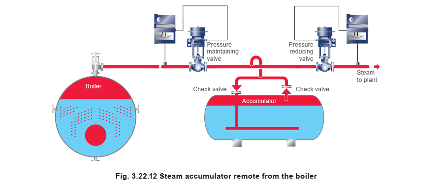
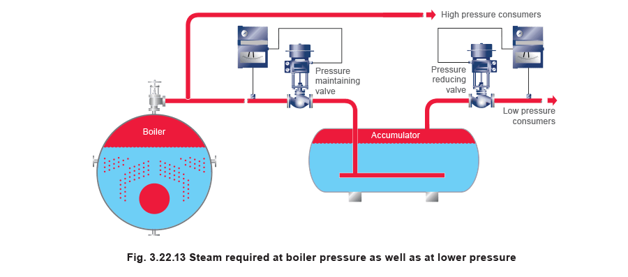
Figure 3.22.13 shows an arrangement where steam at boiler pressure is required as well as steam at a lower pressure.
Some process applications cannot tolerate low pressure steam, and steam at boiler pressure may be required at all times (typically for a drying process). If a peak load is caused by the high pressure users, the pressure maintaining valve in Figure 3.22.13 would sense a pressure drop, and modulate towards its seat, thereby reserving high pressure steam for the high pressure users, thus leaving the steam accumulator to supply the low pressure demand during this period. In this way the system supplies a low pressure fluctuating load via the steam accumulator and the maximum possible flowrate for the high pressure load is ensured by the action of the pressure maintaining valve.
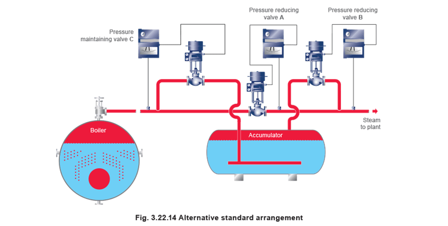
In Figure 3.22.14, the boiler is steaming at its normal design pressure, for example 10 bar, and the steam passes to variable loads which require not more than, for example 5 bar. Pressure reducing valve A is reducing pressure between the boiler header and the distribution main in the plant, responding to the pressure sensed in the 5 bar line.
If the steam demand should exceed the capacity of this supply from the boiler, and the pressure in the low pressure main falls below, for example 4.8 bar, valve B will begin to open and supplement the supply. This draws steam from the steam accumulator, and over a sustained period the steam accumulator pressure will fall. Valve B is responding to the downstream pressure in the distribution main, thus acting as a pressure reducing valve also. Its capacity should match the discharge rate permitted for the steam accumulator, and it will be smaller than pressure reducing valve A.
Valve C is a pressure-maintaining valve, responding to the boiler pressure. If the pressure rises because of reduced demand from the plant, pressure-maintaining valve C opens. Steam is then admitted to the steam accumulator that is recharged towards its maximum pressure, a little below boiler pressure. Pressure reducing valve B will be closed at this time because the plant is receiving sufficient steam through the (partially closed) pressure reducing valve A.
Practical considerations for steam accumulators
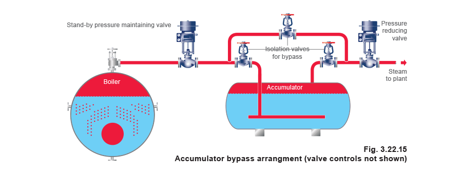
Bypasses
In any plant, the engineering manager must endeavour to provide at least a minimum service in the event that the steam accumulator and its associated equipment either requires maintenance or breaks down.
This will include the provision of adequate and safe isolation of the accumulator with valves, and perhaps some means of protecting the boiler from overload if large changes in demand cannot be avoided. The most obvious solution here is a stand-by pressure-maintaining valve.
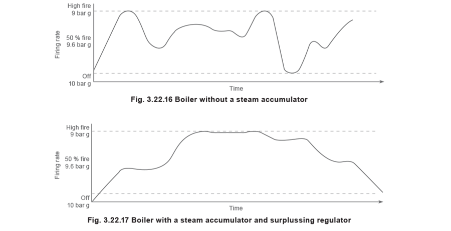
Effects on the boiler firing rate
The steam accumulator and pressure maintaining valve together protect the boiler from overload conditions and allow the boiler to operate properly up to its design rating. This is important to achieve good efficiencies and at the same time to supply clean, dry, saturated steam. Figures 3.22.16 and 3.22.17 illustrate respectively the firing rate without a steam accumulator and the firing rate with a steam accumulator.
Steam quality
When correctly designed and operated, steam from a steam accumulator is always clean, and has a dryness fraction quite close to 1. The steam accumulator is designed with a large water surface and sufficient steam space in order to produce high quality steam almost instantaneously during periods of peak demand. In the case of some vertical steam accumulators the steam space is enlarged to compensate for the smaller water surface.
Water
Water in the steam accumulator is steam that has condensed and is therefore clean and pure, with a typical TDS level of 20 - 100 ppm (compared with a shell boiler TDS of seldom less than 2 000 ppm) which promotes a clean and comparatively stable water surface. Steam accumulators are sometimes used to ensure clean steam is provided where steam is in direct contact with the product; as in hospital and industrial sterilisers, textile finishing and certain applications within the food and drinks industry.
Once the accumulator has been filled with water, and at normal running conditions, water additions and overflow rates are very small indeed.
- If superheated steam is used, the amount of water to be added would be related to the amount of superheat, but since the specific heat of superheated steam is lower than water, it will have a smaller effect on changes in water level.
- If saturated steam is used, the increase in water level is simply a function of heat loss from the vessel. With proper insulation, heat loss is minimal, so the increase in water level, and hence overflow through the steam trap (used as a level limiting device) is also minimal.
Steam accumulator designs
The steam accumulators described and illustrated in this Module have been large and of a horizontal configuration. Steam accumulators are always designed and manufactured to suit the application, and vessels of only 1 m diameter are not uncommon. It is also usual for the smaller steam accumulators to be of a vertical configuration (although large vertical steam accumulators exist). Either configuration can maintain the same values of storage and discharge rate, and it may be easier to find space for a vertical unit.
The storage vessel
This is usually the most expensive part of a steam accumulator system, and will be individually designed for each application. It must be designed to hold the water/steam at the temperatures that are required for the plant. For industrial plant this typically means between 5 and 30 bar, although power station units may be rated up to 150 bar.
Typically the ratio of diameter to total length is between 1.4 to 1.6, but this can vary substantially depending on site conditions.
Steam accumulators are generally cylindrical in form with elliptical ends, as this is structurally the most effective shape. They will be manufactured from boiler plate. In Europe the design and construction will comply with the European Pressure Equipment Directive 97/23/EC.
The greater the acceptable pressure differential between the boiler pressure and the plant pressure, the greater the proportion of flash steam, and hence the lower the live steam capacity required.
In addition to the live storage capacity, the vessel must have:
- Sufficient water in the bottom of the vessel, under minimum conditions, to accommodate and cover the steam injectors
- Sufficient clearance above the water under fully charged conditions to give a reasonable surface area for steam release. This is important because the instantaneous steam release velocity alone could be the final criteria if the peak loads are heavy and abrupt.
Justifying the cost of an accumulator
There are several ways in which the capital cost of an accumulator installation can be justified, and they will often pay back in a short period of time. The following points should be considered during an initial analysis.
- Compare the capital cost of a boiler-only installation to meet the peak demand, with that of a smaller boiler used with an accumulator
- Estimate the fuel savings as a result of a smaller boiler operating closer to its maximum output and on a steadier load. In a recent case study, a brewery calculated a 10% fuel saving and a payback period of approximately 18 months
- As a result of levelling out the peaks and troughs of steam generation, determine if the unit cost of the fuel will be less. It may then be possible to contract for a lower maximum supply rate
- Estimate the financial advantage of reduced maintenance on boiler plant, steam control valves, and the steam using equipment. These benefits will result from a steadier boiler load and better quality steam.
Conclusion
Steam accumulators are not old fashioned relics from the past. Indeed, far from it. Steam accumulators have been installed throughout modern industry including bio-technology, hospital and industrial sterilisation, product testing rigs, printing and food manufacturing, as well as more traditional industries such as breweries and dyehouses.
Modern boilers have become smaller and there is also an increase in the use of small water-tube boilers, coil boilers and annular boilers, all of which are efficient, but which reduce the thermal capacity of the system, and make it vulnerable to peak load problems.
There are many further applications for steam accumulators. For long term peaks which the boiler plant must ultimately handle, a steam accumulator can be used to store, for example, 5 minutes of the peak flowrate, allowing time for the boiler plant to reach the appropriate output safely. Steam accumulators can also be used with electrode or immersion heater boilers so that steam can be generated off peak, stored, and used during peak times. The possibilities are endless.
In summary, the steam accumulator is an efficient tool, as it may well provide the most cost effective way of supplying steam to a batch process.
Acknowledgement
Spirax Sarco acknowledges the help and information provided by:
Wilson Steam Storage Ltd., Chesterfield, Derbyshire, S41 8NG