The Boiler House

Contents
Shell Boilers
Overview of the different types of shell boiler with layouts, heat and steam release considerations plus pressure and output limitations.
Shell boilers may be defined as those boilers in which the heat transfer surfaces are all contained within a steel shell. Shell boilers may also be referred to as ‘fire tube’ or ‘smoke tube’ boilers because the products of combustion pass through the boiler tubes, which in turn transfer heat to the surrounding boiler water.
Several different combinations of tube layout are used in shell boilers, involving the number of passes the heat from the boiler furnace will usefully make before being discharged.
Figures 3.2.1a and 3.2.1b show a typical two-pass boiler configuration.
Figure 3.2.1a shows a dry back boiler where the hot gases are reversed by a refractory lined chamber on the outer plating of the boiler.

Figure 3.2.1b shows a more efficient method of reversing the hot gases through a wet back boiler configuration. The reversal chamber is contained entirely within the boiler. This allows for a greater heat transfer area, as well as allowing the boiler water to be heated at the point where the heat from the furnace will be greatest - on the end of the chamber wall.
It is important to note that the combustion gases should be cooled to at least 420°C for plain steel boilers and 470°C for alloy steel boilers before entering the reversal chamber. Temperatures in excess of this will cause overheating and cracking of the tube end plates. The boiler designer will have taken this into consideration, and it is an important point if different fuels are being considered.
Several different types of shell boilers have been developed, which will now be looked at in more detail.
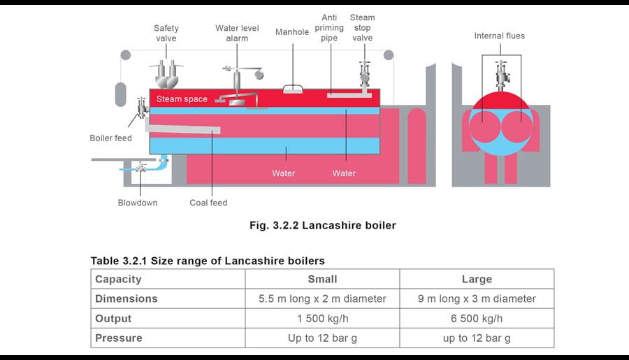
Lancashire boiler
Sir William Fairbairn developed the Lancashire boiler in 1844 from Trevithick’s single flue Cornish boiler. Although only a few are still in operation, they were ubiquitous and were the predecessors of the sophisticated and highly efficient boilers used today.
The Lancashire boiler comprised a large steel shell usually between 5 - 9 m long through which passed two large-bore furnace tubes called flues. Part of each flue was corrugated to take up the expansion when the boiler became hot, and to prevent collapse under pressure. A furnace was installed at the entrance to each flue, at the front end of the boiler. Typically, the furnace would be arranged to burn coal, being either manually or automatically stoked.
The hot gaseous products of combustion passed from the furnace through the large-bore corrugated flues. Heat from the hot flue gases was transferred into the water surrounding these flues.
The boiler was in a brickwork setting which was arranged to duct the hot gases emerging from the flues downwards and beneath the boiler, transferring heat through the bottom of the boiler shell, and secondly back along the sides of the boiler before exiting through the stack.
These two side ducts met at the back of the boiler and fed into the chimney.
These passes were an attempt to extract the maximum amount of energy from the hot product gases before they were released to atmosphere.
Later, the efficiency was improved by the addition of an economiser. The gas stream, after the third pass, passed through the economiser into the chimney. The economiser heated the feedwater and resulted in an improvement in thermal efficiency.
One of the disadvantages of the Lancashire boiler was that repeated heating and cooling of the boiler, with the resultant expansion and contraction that occurred, upset the brickwork setting and ducting. This resulted in the infiltration of air, which upset the furnace draught.
These boilers would now be very expensive to produce, due to the large amounts of material used and the labour required to build the brick setting.
The large size and water capacity of these boilers had a number of significant advantages:
- Sudden large steam demands, such as a pit-winding engine being started, could easily be tolerated because the resulting reduction in boiler pressure released copious amounts of flash steam from the boiler water held at saturation temperature.
These boilers may well have been manually stoked, consequently the response to a decrease in boiler pressure and the demand for more fuel would have been slow.
- The large volume of water meant that although the steaming rate might vary widely, the rate of change of the water level was relatively slow.
Water level control would again have been manual, and the operator would either start a reciprocating, steam powered feedwater pump, or adjust a feedwater valve to maintain the desired water level.
- The low level alarm was simply a float that descended with the water level, and opened a port to a steam whistle when a pre-determined level was reached.
- The large water surface area in relation to the steaming rate meant that the rate at which steam was released from the surface (expressed in terms of kg per square metre) was low.
This low velocity meant that, even with water containing high concentrations of Total Dissolved Solids (TDS), there was plenty of opportunity for the steam and water particles to separate and dry steam to be supplied to the plant.
As control systems, materials, and manufacturing techniques have become more sophisticated, reliable and cost effective, the design of boiler plant has changed.
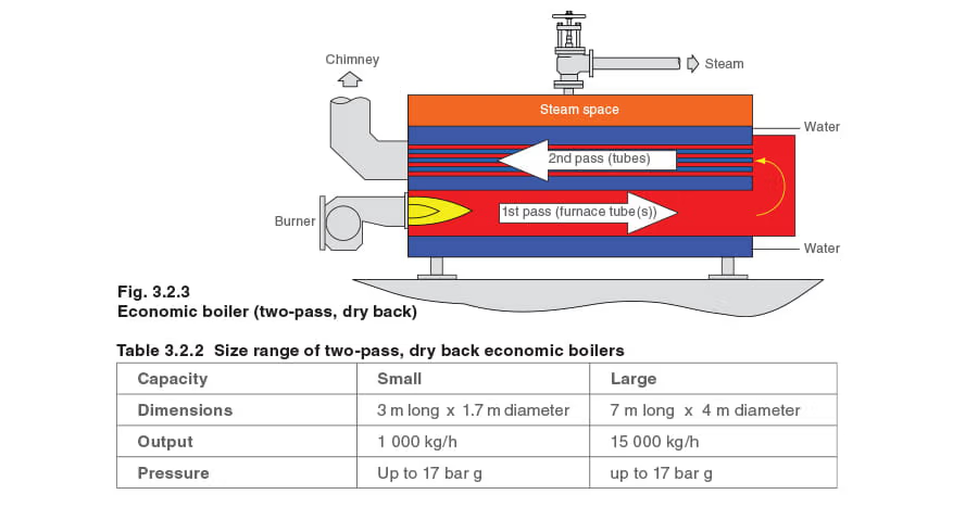
Economic boiler (two-pass, dry back)
The two-pass economic boiler was only about half the size of an equivalent Lancashire boiler and it had a higher thermal efficiency. It had a cylindrical outer shell containing two arge-bore corrugated furnace flues acting as the main combustion chambers. The hot flue gases passed out of the two furnace flues at the back of the boiler into a brickwork setting (dry back) and were deflected through a number of small-bore tubes arranged above the large-bore furnace flues. These small bore tubes presented a large heating surface to the water. The flue gases passed out of the boiler at the front and into an induced draught fan, which passed them into the chimney.
Economic boiler (three-pass, wet back)
A further development of the economic boiler was the creation of a three-pass wet back boiler which is a standard configuration in use today, (see Figure 3.2.4).
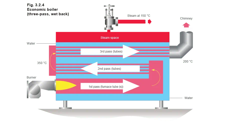
This design has evolved as materials and manufacturing technology has advanced: thinner metal tubes were introduced allowing more tubes to be accommodated, the heat transfer rates to be improved, and the boilers themselves to become more compact.
Typical heat transfer data for a three-pass, wet back, economic boiler is shown in Table 3.2.3.

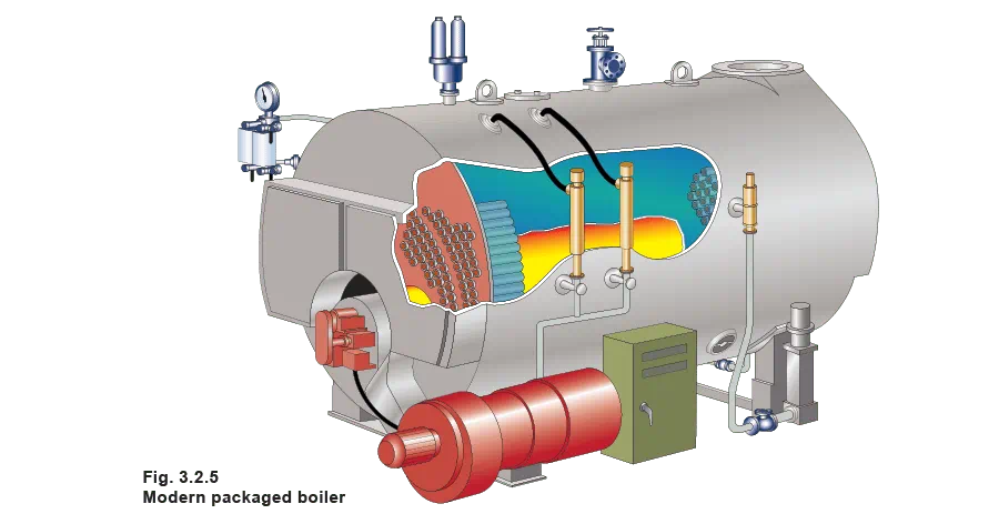
Packaged boiler
In the early 1950s, the UK Ministry of Fuel and Power sponsored research into improving boiler plant. The outcome of this research was the packaged boiler, resulting from further development on the three-pass economic wet back boiler. Mostly, these boilers were designed to use oil rather than coal.
The packaged boiler is so called because it comes as a complete package with burner, level controls, feedpump and all necessary boiler fittings and mountings. Once delivered to site it requires only the steam, water, and blowdown pipework, fuel supply and electrical connections to be made for it to become operational.
Development has also had a significant effect on the physical size of boilers for a given output:
- Manufacturers wanted to make the boilers as small as possible to save on materials and hence keep their product competitive.
- Efficiency is aided by making the boiler as small as it is practical; the smaller the boiler and the less its surface area, the less heat is lost to the environment.
To some extent the universal awareness of the need for insulation, and the high performance of modern insulating materials, reduces this issue.
- Consumers wanted the boilers to be as small as possible to minimise the amount of floor space needed by the boiler house, and hence increase the space available for other purposes.
- Boilers with smaller dimensions (for the same steam output) tend to be lower in capital cost. Table 3.2.4 demonstrates this, and other factors.
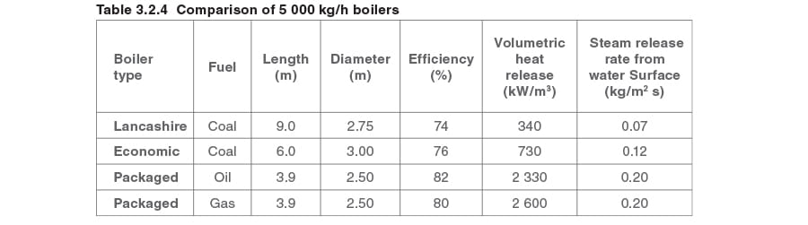
Volumetric heat release (kW/m3)
This factor is calculated by dividing the total heat input by the volume of water in the boiler. It effectively relates the quantity of steam released under maximum load to the amount of water in the boiler. The lower this number, the greater the amount of reserve energy in the boiler.
Note that the figure for a modern boiler relative to a Lancashire boiler, is larger by a factor of almost eight, indicating a reduction in stored energy by a similar amount. This means that a reduced amount of stored energy is available in a modern boiler. This development has been made possible by control systems which respond quickly and with appropriate actions to safeguard the boiler and to satisfy demand.
Steam release rate (kg/m2s)
This factor is calculated by dividing the amount of steam produced per second by the area of the water plane. The lower this number, the greater the opportunity for water particles to separate from the steam and produce dry steam.
Note the modern boiler’s figure is larger by a factor of almost three. This means that there is less opportunity for the separation of steam and water droplets.
This is made much worse by water with a high TDS level, and accurate control is essential for efficiency and the production of dry steam.
At times of rapidly increasing load, the boiler will experience a reduction of pressure, which, in turn, means that the density of the steam is reduced, and even higher steam release rates will occur, and progressively wetter steam is exported from the boiler.
Four-pass boilers
Four-pass units are potentially the most thermally efficient, but fuel type and operating conditions may prevent their use. When this type of unit is fired at low demand with heavy fuel oil or coal, the heat transfer from the combustion gases can be very large. As a result, the exit flue gas temperature can fall below the acid dew point, causing corrosion of the flues and chimney and possibly of the boiler itself. The four-pass boiler unit is also subject to higher thermal stresses, especially if large load swings suddenly occur; these can lead to stress cracks or failures within the boiler structure. For these reasons, four-pass boilers are unusual.
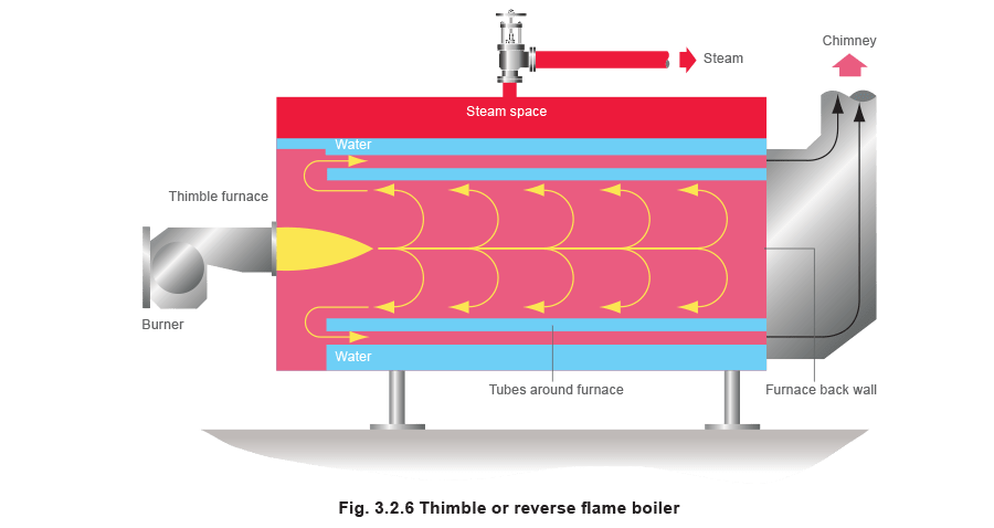
Reverse flame/thimble boiler
This is a variation on conventional boiler design. The combustion chamber is in the form of a thimble, and the burner fires down the centre. The flame doubles back on itself within the combustion chamber to come to the front of the boiler. Smoke tubes surround the thimble and pass the flue gases to the rear of the boiler and the chimney.
Pressure and output limitations of shell type boilers
The stresses that may be imposed on the boiler are limited by national standards. Maximum stress will occur around the circumference of a cylinder. This is called ‘hoop’ or ‘circumferential’ stress. The value of this stress can be calculated using Equation 3.2.1:
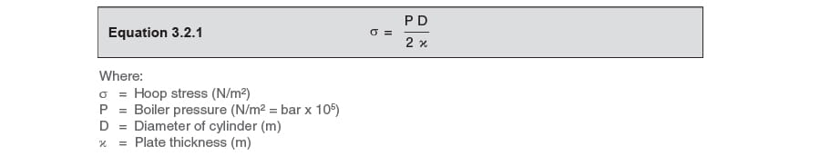
From this it can be deduced that hoop stress increases as diameter increases. To compensate for this the boiler manufacturer will use thicker plate. However, this thicker plate is harder to roll and may need stress relieving with a plate thickness over 32 mm.
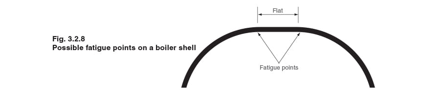
One of the problems in manufacturing a boiler is in rolling the plate for the shell. Boilermakers’ rolls, as shown in Figures 3.2.7 and 3.2.8, cannot curve the ends of the plate and will, hence, leave a flat:
- Roll A is adjusted downwards to reduce radius of the curvature.
- Rolls B and C are motorised to pull the plate through the rolls.
- The rolls cannot curve the ends of the plate

When the plates are welded together and the boiler is pressurised, the shell will assume a circular cross section. When the boiler is taken off-line, the plates will revert to the ‘as rolled’ shape. This cycling can cause fatigue cracks to occur some distance away from the shell welds. It is a cause for concern to boiler inspectors who will periodically ask for all the boiler lagging to be removed and then use a template to determine the accuracy of the boiler shell curvature.
Obviously, this problem is of more concern on boilers that experience a lot of cycling, such as being shutdown every night, and then re-fired every morning.
Pressure limitation
Heat transfer through the furnace tubes is by conduction. It is natural that thick plate does not conduct heat as quickly as thin plate. Thicker plate is also able to withstand more force.
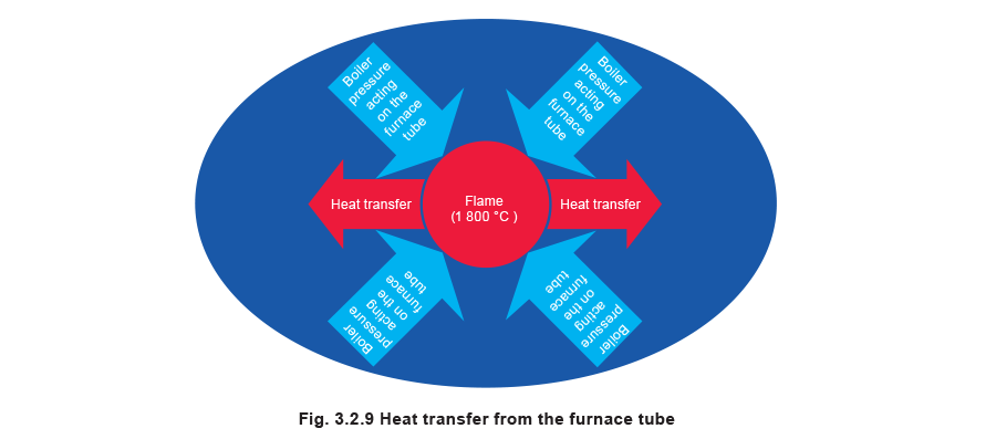
This is of particular importance in the furnace tubes where the flame temperature may be up to 1 800°C, and a balance must be struck between:
- A thicker plate, which has the structural strength to withstand the forces generated by pressure in the boiler.
- A thinner plate, which has the ability to transfer heat more quickly.
The equation that connects plate thickness to structural strength is Equation 3.2.1:
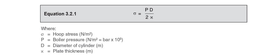
Equation 3.2.1 shows that as the plate thickness gets less, the stress increases for the same boiler pressure.
The equation that connects plate thickness to heat transfer is Equation 2.5.1:

Equation 2.5.1 shows that as the plate thickness gets less, the heat transfer increases. By transposing both equations to reflect the plate thickness.
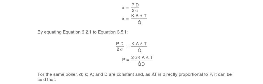
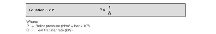
For any one boiler, if the heat transfer rate (q_dot - body text.jpg) is increased, the maximum allowable boiler pressure is reduced.
A compromise is reached with a furnace tube wall thickness of between 18 mm and 20 mm. This translates to a practical pressure limit for shell boilers of around 27 bar.
Output limitation
Shell boilers are manufactured as packaged units with all the ancillary equipment fixed into position. After manufacture, the packaged boiler must be transported to site and the largest boiler which can be transported by road in the UK has an output of around 27 000 kg/h.
If more than 27 000 kg/h is required, then multi-boiler installations are used. However, this has the advantage of providing better security of supply and improved plant turndown.

Summary
Today’s highly efficient and responsive shell boiler is the result of more than 150 years of development in:
- Boiler and burner design.
- Material science.
- Boiler manufacturing techniques.
- Control systems.
To guarantee its successful and efficient operation, the user must:
- Know the conditions, environment, and demand characteristics of the plant, and accurately specify these conditions to the boiler manufacturer.
- Provide a boiler house layout and installation that promotes good operation and maintenance.
- Select the control systems that allow the boiler to operate safely and efficiently.
- Select the control systems that will support the boiler in supplying dry steam to the plant at the required pressure(s) and flowrate(s).
- Identify the fuel to be used and, if necessary, where and how the fuel reserve is to be safely stored.
Advantages of shell boilers:
- The entire plant may be purchased as a complete package, only needing securing to basic foundations, and connecting to water, electricity, fuel and steam systems before commissioning. This means that installation costs are minimised.
- This package arrangement also means that it is simple to relocate a packaged shell boiler.
- A shell boiler contains a substantial amount of water at saturation temperature, and hence has a substantial amount of stored energy which can be called upon to cope with short term, rapidly applied loads.
This can also be a disadvantage in that when the energy in the stored water is used, it may take some time before the reserve is built up again.
- The construction of a shell boiler is generally straight forward, which means that maintenance is simple.
- Shell boilers often have one furnace tube and burner. This means that control systems are fairly simple.
- Although shell boilers may be designed and built to operate up to 27 bar, the majority operate at 17 bar or less. This relatively low pressure means that the associated ancillary equipment is easily available at competitive prices.
Disadvantages of shell boilers:
The package principle means that approximately 27 000 kg/h is the maximum output of a shell boiler. If more steam is required, then several boilers need to be connected together.
The large diameter cylinders used in the construction of shell boilers effectively limit their operating pressure to approximately 27 bar. If higher pressures are needed, then a water-tube boiler is required.