Steam Traps and Steam Trapping

Contents
Thermodynamic Steam Traps
Thermodynamic steam traps have a unique operating principle which relies on the dynamics of water and flash steam. They are simple, robust and reliable and can operate up to very high temperatures and pressures. Their construction, use and benefits are detailed here.
Traditional thermodynamic steam trap
The thermodynamic trap is an extremely robust steam trap with a simple mode of operation. The trap operates by means of the dynamic effect of flash steam as it passes through the trap, as depicted in Figure 11.4.1. The only moving part is the disc above the flat face inside the control chamber or cap.
On start-up, incoming pressure raises the disc, and cool condensate plus air is immediately discharged from the inner ring, under the disc, and out through three peripheral outlets (only 2 shown, Figure 11.4.1, i).
Hot condensate flowing through the inlet passage into the chamber under the disc drops in pressure and releases flash steam moving at high velocity. This high velocity creates a low pressure area under the disc, drawing it towards its seat (Figure 11.4.1, ii).
At the same time, the flash steam pressure builds up inside the chamber above the disc, forcing it down against the incoming condensate until it seats on the inner and outer rings. At this point, the flash steam is trapped in the upper chamber, and the pressure above the disc equals the pressure being applied to the underside of the disc from the inner ring. However, the top of the disc is subject to a greater force than the underside, as it has a greater surface area.
Eventually the trapped pressure in the upper chamber falls as the flash steam condenses. The disc is raised by the now higher condensate pressure and the cycle repeats (Figure 11.4.1, iv).
The rate of operation depends on steam temperature and ambient conditions. Most traps will stay closed for between 20 and 40 seconds. If the trap opens too frequently, perhaps due to a cold, wet, and windy location, the rate of opening can be slowed by simply fitting an insulating cover onto the top of the trap.
Advantages of the thermodynamic steam trap
- Thermodynamic traps can operate across their entire working range without any adjustment or change of internals.
- They are compact, simple, lightweight and have a large condensate capacity for their size.
- Thermodynamic traps can be used on high pressure and superheated steam and are not affected by waterhammer or vibration. The all stainless steel construction offers a high degree of resistance to corrosive condensate.
- Thermodynamic traps are not damaged by freezing and are unlikely to freeze if installed with the disc in a vertical plane and discharging freely to atmosphere. However, operation in this position may result in wear of the disc edge.
- As the disc is the only moving part, maintenance can easily be carried out without removing the trap from the line.
- The audible 'click' which occurs as the trap opens and closes makes trap testing very straightforward.

Disadvantages of the thermodynamic steam trap
- Thermodynamic steam traps will not work positively on very low differential pressures, as the velocity of flow across the underside of the disc is insufficient for lower pressure to occur. They are subjected to a minimum inlet pressure (typically 0.25 bar g) but can withstand a maximum backpressure of 80% of the inlet pressure.
- Thermodynamic traps can discharge a large amount of air on 'start-up' if the inlet pressure builds up slowly. However, rapid pressure build-up will cause high velocity air to shut the trap in the same way as steam, and it will 'air-bind'. In this case a separate thermostatic air vent can be fitted in parallel with the trap. Modern thermodynamic steam traps can have an inbuilt anti-air-binding disc which prevents air pressure building up on top of the disc and allows air to escape, (Figure 11.4.3).
- The discharge of the trap can be noisy and this factor may prohibit the use of a thermodynamic trap in some locations, e.g. outside a hospital ward or operating theatre. If this is a problem, it can easily be fitted with a diffuser which considerably reduces the discharge noise.
- Care should be taken not to oversize a thermodynamic trap as this can increase cycle times and induce wear. Mains drainage applications often only need to be fitted with low capacity versions, providing proper consideration is given to siting the drain pockets correctly.

Impulse steam trap
The impulse trap (as shown in Figure 11.4.4) consists of a hollow piston (A) with a piston disc (B) working inside a tapered piston (C) which acts as a guide. At 'start-up' the main valve (D) rests on the seat (E) leaving a passage of flow through the clearance between piston and cylinder and hole (F) at the top of the piston. Increasing flow of air and condensate will act on the piston disc and lift the main valve off its seat to give increased flow. Some condensate will also flow through the gap between the piston and disc, through E and away to the trap outlet.
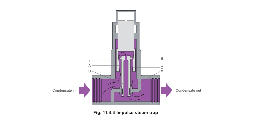
As the condensate approaches steam temperature some of it flashes to steam as it passes through the gap. Although this is bled away through hole F it does create an intermediate pressure over the piston, which effectively positions the main valve to meet the load. The trap can be adjusted by moving the position of piston (B) relative to the seat, but the trap is affected by significant backpressure. It has a substantial capacity, bearing in mind its small size. Conversely, the trap is unable to give complete shut-off and will pass steam on very light loads. The main problem however is the fine clearance between the piston and cylinder. This is readily affected by the dirt normally found in a steam system. The use of impulse traps is relatively limited so they are not considered in some subsequent sections of this Module.
Advantages of the impulse steam trap
- Impulse traps have a substantial condensate handling capacity for their size.
- They will work over a wide range of steam pressures without any change in valve size and can be used on high pressure and superheated steam.
- They are good at venting air and cannot ‘air-bind’.
Disadvantages of the impulse steam trap
- Impulse traps cannot give a dead tight shut-off and will blow steam on very light loads.
- They are easily affected by any dirt which enters the trap body due to the extremely small clearance between the piston and the cylinder.
- The traps can pulsate on light load causing noise, waterhammer and even mechanical damage to the valve itself.
- They will not work against a backpressure which exceeds 40% of the inlet pressure.
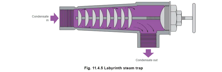
Labyrinth steam trap
A simple form of the labyrinth trap is shown in Figure 11.4.5. It consists of a series of baffles which can be adjusted by means of a handwheel. Hot condensate passing between the first baffle and the trap body is subject to a drop in pressure and some of it 'flashes' to steam. The space around the next baffle has to cope with an increased volume of hot condensate and prevents the escape of live steam. The baffle plates can be moved either in or out using the handwheel, which alters their position relative to the body, effectively altering the overall size of the orifice.
Advantages of the labyrinth steam trap
- This type of trap is comparatively small in relation to its capacity and there is little potential for mechanical failure since there are no automatic parts.
Disadvantages of the labyrinth steam trap
- The labyrinth trap has to be adjusted manually whenever there is a significant variation in either steam pressure or condensate load. If the setting is not right for the prevailing conditions, steam wastage or waterlogging of the steam space will occur (like a fixed orifice trap).
Fixed orifice traps
These are devices containing a hole of predetermined diameter to allow a calculated amount of condensate to flow under specific pressure conditions. In practice, condensate loads and steam pressures can vary considerably. For instance, start-up and running loads can differ considerably along with steam pressure which will change due to the actions of temperature controls. These varying conditions can result in the fixed orifice either holding back condensate in the process or passing live steam, which can affect plant performance and compromise safety.
Fixed orifices are often sized on running conditions, so that they hold back enough condensate and do not pass steam. If this is so, at start-up, they are undersized to a greater degree and the steam space stands a good chance of waterlogging.
The alternative is to size them so as not to waterlog during start-up. The hole is then effectively oversized for running conditions, and the device will pass steam. The size of hole is usually a compromise between the two conditions, such that, at some points in between, the hole is correctly sized.
Corrosion and service life of plant
Continual waterlogging significantly increases the risk of corrosion in the steam space. It is not unusual to find that after fitting fixed orifice traps, plant service life is reduced below that which may be expected with proper steam traps.
A proper steam trap should be able to achieve just sufficient capacity at all pressures and flowrates present in the application. It can then pass hot condensate without leaking steam under any condition. To achieve this, the size of the hole must vary in the trap. It must be large enough to meet the worst condition, and then have some means of reducing the effective orifice flow area when the capacity becomes too great. This exactly describes the operation of a steam trap.
Advantages of a fixed orifice trap
- Can be used successfully when pressures and loads are constant.
- There are no moving parts.
Disadvantages of a fixed orifice trap
- If sized on running load, fixed orifice traps will waterlog on start-up, reducing plant performance over this period, increasing start-up times and the risk of corrosion.
- If sized on start-up load, fixed orifice traps will waste steam when the plant is running, effectively increasing running costs.
- Fixed orifice traps often block with dirt due to the small size of orifice.
- The cost of replacing a heat exchanger due to corrosion will be far higher than the cost of replacing the fixed orifice trap with a steam trap.
Note: Fixed orifice traps are not recommended for draining condensate from any application susceptible to varying load conditions.
Highlighted products

BT6 Balanced Pressure Steam Trap
The BT6 316L stainless steel balanced pressure steam trap is specifically designed for hygienic applications including steam barriers, CIP/SIP and process vessel drainage, sterilisers and autoclaves, and culinary steam mains drainage.

FTS14 Ball Float Steam Trap
The requirement for 316 stainless steel is gradually being extended to secondary side media such as steam and hot water.

TD62M and TD62LM
The TD62LM and TD62M are maintainable high pressure thermodynamic steam traps with integral strainer and a replaceable seat to ease maintenance.