Steam Traps and Steam Trapping

Contents
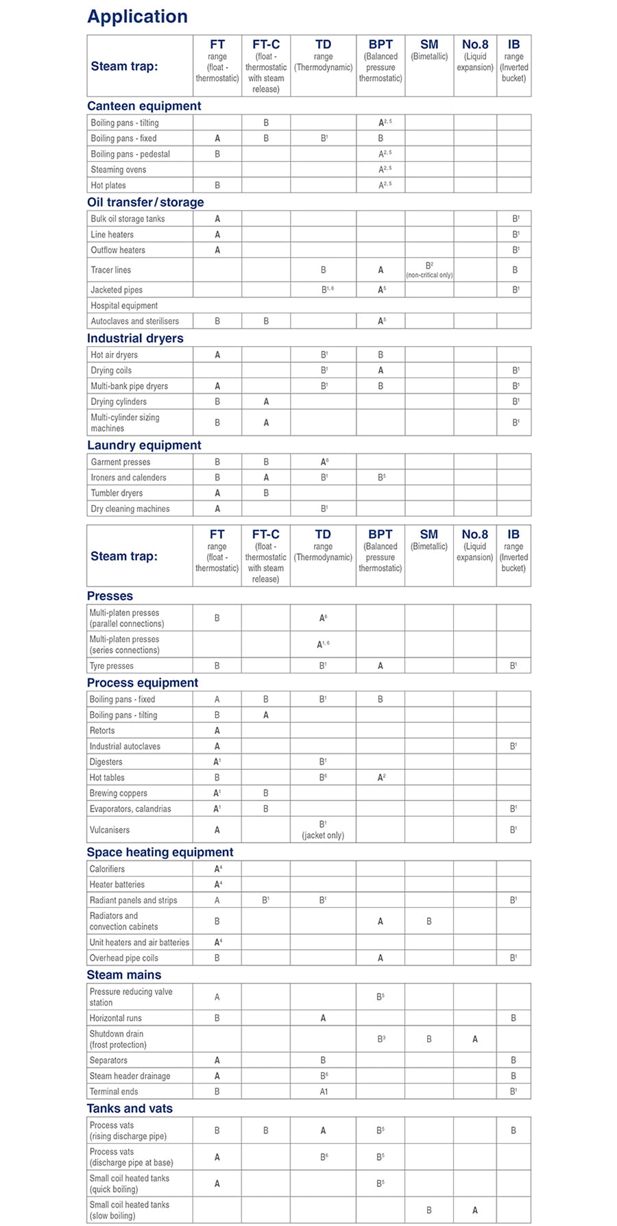
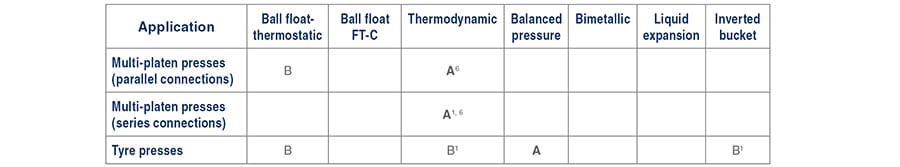
Selecting Steam Traps - Canteen Equipment; Oil Transfer/Storage; Hospital Equipment
Selection tables and advice on trap selection for a range of different processes are included in this tutorial, including steaming ovens, bulk storage tanks and autoclaves.
Selecting Steam Traps
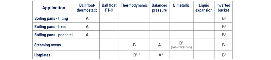
Key:
A - Best choice.
B - Acceptable alternative.
1 - With air vent in parallel.
2 - At end of unlagged cooling leg. Minimum length 1 m.
3 - Use special tracing traps which offer fixed temperature discharge option.
4 - If the equipment is temperature controlled, a condensate pump and trap combination may be required.
5 - With close to steam temperature capsule.
6 - Fitted with anti-air-binding disc.
Canteen Equipment
A - Best choice, B - Acceptable alternative,
1 (parallel air vent), 2 (with 1 m cooling leg), 5 ('near-to-steam' capsule).
Canteen boiling pans
Although similar in construction to process jacketed pans, canteen boiling pans do not normally have the same need for rapid heating, consequently the steam pressure is normally lower. Condensate loads will normally be much lower. Whilst air and condensate removal are not so critical, air vents can still be useful in reducing heat-up times.
Tilting boiling pans
Figure 11.6.1 shows a balanced pressure thermostatic trap, draining a slow boiling tilting pan. A balanced pressure air vent (fitted as shown) will speed up the boil of, for example, 140 litres of soup by about 20 minutes. If faster cooking would be an advantage, an air vent should be fitted. A good alternative to the balanced pressure steam trap is a float trap with steam lock release.

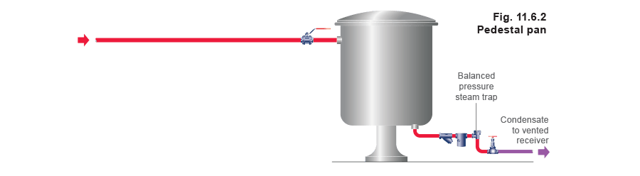
Pedestal boiling pans
The correct way to drain pedestal boiling pans is to use a balanced pressure thermostatic trap and strainer. For efficient operation this should be fitted about 1 m away from the outlet at the end of the cooling leg (Figure 11.6.2). There is usually no need to fit an air vent on this type of pan.
Steaming ovens and hotplates
Figure 11.6.3 shows an ideal layout for draining and air venting steaming ovens. There are three vital features:
• The steam inlet must be drained just before the inlet valve by a balanced pressure thermostatic trap.
• Each compartment outlet must have a similar trap direct on to the outlet, but without a strainer (to let the greasy condensate pass through before the grease cools).
• The traps draining the compartments, and the air vents, should be fitted with near-to-steam elements. The ovens should be blown through with steam after cooking has finished.
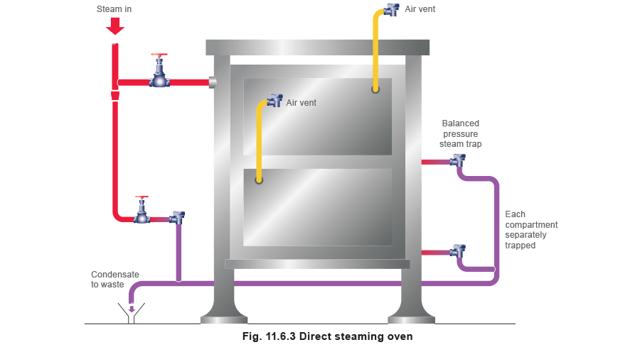
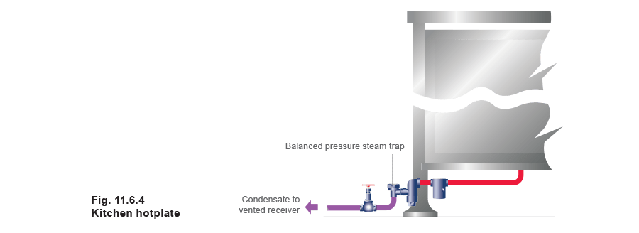
Figure 11.6.4 shows a kitchen hotplate fitted with a Fig 5 type strainer, close coupled to a balanced pressure thermostatic steam trap, an ideal combination for this application.
Oil Transfer / Storage
A - Best choice, B - Acceptable alternative,
1 (parallel air vent), 2 (with 1 m cooling leg), 5 (‘near-to-steam’ capsule), 6 (anti-air-binding disc).
Bulk storage tanks
Oil and other fluids are stored in tanks that are heated by pipe coils or other forms of heating, either alone, or in combination with outflow heaters, to provide the correct temperature for pumping. Line heaters raise the temperature of fuel oil to that required for burning or for process use.
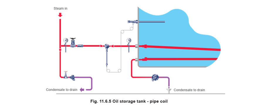
There are several ways to heat small to medium sized storage tanks, such as with pipe coils (Figure 11.6.5) spread across the bottom of the tank, or with ‘bayonet’ or ‘field’ heaters (Figure 11.6.6).
In these situations a large pipe, sealed at both ends, is fixed through the side of the tank. Steam is fed to the remote end by an internal pipe and condensate is removed from the nearest end. However, on larger tanks, one of the more widely used methods is the fitting of a number of special heaters served from an internal ring main as in Figures 11.6.7 and 11.6.8.
With all coil configurations it is essential that each pipe section or each heater is separately trapped.
Long coils are susceptible to waterhammer, as they will collect condensate along their length. Because of this, it makes sense that coils are designed with a constant fall in the direction of steam flow. The modern float-thermostatic trap is equipped to withstand high levels of waterhammer, but if the symptoms are extreme, an inverted bucket trap or balanced pressure trap is a good choice. It may be necessary to lag float-thermostatic traps to protect them against damage by freezing. The inverted bucket trap may require a separate air vent to be fitted in parallel to remove air from the coil on start-up.
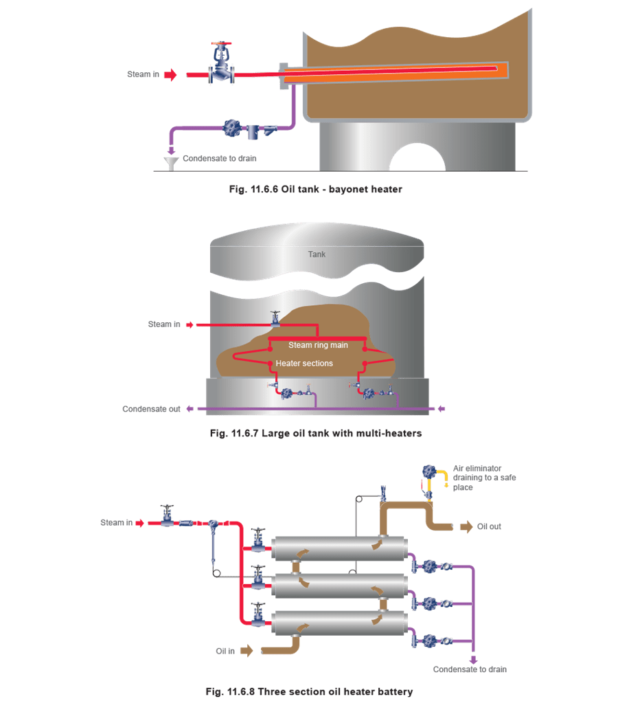
Oil heater batteries
These are single or multi-stage heat exchangers and should be treated in a similar manner to outflow heaters. Each stage should be individually trapped and since they are often fitted indoors where the traps are not likely to freeze, float-thermostatic traps are the best choice.
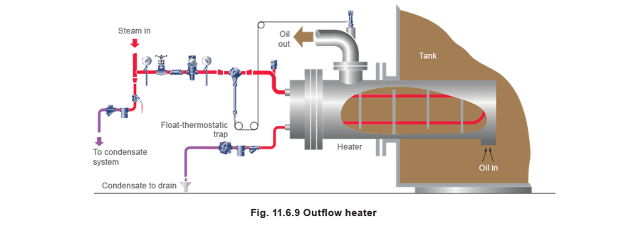
Outflow heaters
An outflow heater is a shell and tube heat exchanger installed in the side of a storage tank, which heats the oil locally as it is pumped out of the tank. Automatic temperature control is usual and Figure 11.6.9 shows a Spirax Sarco self-acting control with the sensor in the oil outlet, actuating a valve in the steam supply.
The first choice is to use a float-thermostatic trap. If exposed to the elements, it should be insulated. It is normal for condensate to be wasted due to the risk of contamination by the oil, but if condensate is being returned and lifted up to a return main it is not recommended that it is lifted by its own pressure, as flooding and waterhammer are likely at light loads. A pump / trap installation may be used under these conditions.
Tracer lines
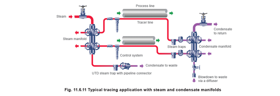
Tracer lines should be arranged to fall in the direction of steam flow and should not exceed 25 metres in length for 10 mm tracers or 50 metres for all larger sizes, each length being drained by a balanced pressure thermostatic tracing trap or a thermodynamic trap. It is preferable to run single tracers near the bottom of the product line, and where it is necessary to pass flanges, this should be done with a horizontal loop to help maintain a continuous fall towards the trap.

Oil pipe tracing is not normally considered ‘critical’, and where condensate is discharged to waste, a bimetallic trap or a balanced pressure thermostatic tracing trap (in the constant temperature discharge mode) can be used. This will conserve energy and prevent unsightly flash steam. However, if critical tracing is considered essential, a thermodynamic or balanced pressure trap, discharging close to steam saturation, should be used.
A convenient method of supplying steam to large numbers of tracers on process lines, and for draining condensate from them, is to use distribution and collection manifolds. These are shown in Figure 11.6.11, along with universal steam traps, and pipeline connectors with integral isolation valves. These allow traps to be changed quickly and without any downtime.
Jacketed pipes
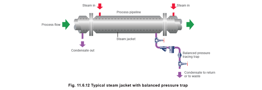
When the temperature of the product is critical (because of the danger of solidification, burning or vaporisation) the complete product pipeline is ‘traced’ with a steam jacket. This application is often seen in ‘sulfur’ plants.
Jacketed pipes are generally constructed in not more than 6 m lengths and ideally, each length should be separately trapped using a balanced pressure thermostatic tracing trap, (Figure 11.6.12), or a TD trap.
It is, however, quite practical to join up to 4 lengths together, but it is important to join the jackets both at the top and bottom (Figure 11.6.13) so that the steam and condensate can flow freely and independently. It is worth noting, since many jacketed pipes are exposed to the elements, that the steel bodies of the thermodynamic and balanced pressure traps are not damaged by freezing.

Hospital Equipment
A - Best choice, B - Acceptable alternative,
5 ('near-to-steam' capsule).
Autoclave and sterilisers

The draining and air venting of modern high vacuum sterilisers is very important and the manufacturer normally supplies the necessary trapping equipment with the machine.
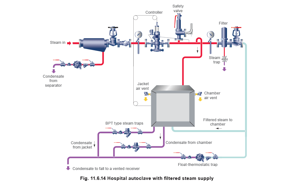
Figure 11.6.14 shows an autoclave supplied with plant steam for the jacket, and filtered steam for the chamber. The steam supplied to the chamber must be dry, so a separator drained by a float-thermostatic trap should be fitted to the steam line. For the chamber a balanced pressure thermostatic trap with near-to-steam capsule can be used successfully. On large units a float-thermostatic trap may be needed. A strainer to protect the trap is important, as it will catch any fibrous material or broken glass. If the steam inlet to the jacket is at the bottom or at one end, an air vent at the top or the far end will give better heating. The jacket may be drained with a balanced pressure thermostatic trap-strainer unit.
On new systems, there is an increasing requirement to use all stainless steel pipework and fittings to comply with European and International standards. In many cases, this will require the use of 316L steam traps.