Steam Traps and Steam Trapping

Contents
Air Venting Applications
Some of the many different applications for air vents are described in this tutorial, including steam mains, bypasses, jacketed vessels and rotating cylinders. Other issues such as venting large volumes of air, group air venting and the substitution of thermostatic steam traps are also considered.
Air vent units in general
The automatic air vent is a valve, thermostatically operated, and installed at a location where steam and air, rather than condensate, will reach it. If the air vent is close coupled to a heater of substantial mass, and which is operating at close to steam temperature, then conducted heat may hold the air vent closed, or at least slow down its operation. It is therefore recommended that any air vent and its connecting pipe should be installed unlagged in order for it to operate correctly.
Under these circumstances, the air vent is best installed at the end of a length of about 300 mm of pipe which can act as a collecting bottle, and which permits a temperature gradient from the heater steam space to the vent. The 'bottles' mentioned in 'Rotating cylinders' can be utilised in this way as air collecting units.
When air vents discharge, they invariably do so with an air / steam mixture. This is often perceived as being pure steam, and the logical conclusion is to believe that the air vent is leaking. If operating normally, the degree of discharge should eventually reduce and cease. If the air vent continues to discharge over a long period without any sign of shutting off, it could well be faulty and would benefit from being inspected and repaired.
Steam trap bypasses
It seems natural to fit manual bypasses around steam traps, usually to be opened at start-up. Since condensate loads at start-up are rarely much more than twice the running load, and traps usually have condensate capacities giving safety factors of considerably more than this, it seems that the real function of bypasses is to discharge air. This allows the condensate to reach the trap.
Bypasses are often found around bucket traps, which are inherently slow to vent air. The assembly can be made both automatic and efficient by simply replacing the manual bypass valve with an automatic air vent. Manual bypasses are easily forgotten about and left open, and are therefore a potential source of steam wastage.
Vacuum breakers
Vacuum breakers may be used to good effect at times of system shutdown when sub-atmospheric pressures may be experienced within steam pipes and apparatus. Strategically placed, they will allow condensate to gravitate down to the drain trapping point. By allowing the complete removal of condensate from any steam system, fear of waterhammer will be removed at the next system start-up.
Saturated steam mains
The steam main is, in effect, a long steam space with a small cross-section. When steam is turned on at the supply end, it moves along the pipe like a piston, pushing the air in front of it. An air vent fitted at the end of the line as in Figure 11.10.13, Module 10, will clear most of the air. The vent is connected at the top of the pipe, or at least at a point above the expected level of condensate.
Superheated steam mains
Superheated steam mains, generally, only require air venting at start-up. An air vent able to withstand high temperatures is required, consequently a bimetallic type would be the best choice.
Jacketed pans
Selecting the air vent location for these applications can be difficult. Air dissolved in the cold product is forced out of solution as the pan warms up, and bubbles appear on the product side of the jacket. Lack of bubbling on the inside skin of the pan reveals cold spots, indicating where air is collecting inside the jacket.
With the combination of the wrong type of steam trap and no air vent, it is likely that bubbling will occur last at the bottom of the jacket near the condensate outlet, and at the top opposite the steam entry point. The best steam trap will be a float type with air vent, placed below the pan, allowing condensate and air to gravitate to the floor, or to a collecting receiver and pump. The air vent is best placed opposite the steam entry point at high level, and a bonafide manufacturer will place a tapping for this purpose, (Figure 11.9.1, Module 9).
A tilting pan requires a float trap with steam lock release feature as the condensate is removed via a dip pipe passing through a rotary joint. If this does not include an air vent, then a separate air vent bypassing the trap will improve the performance. Likewise, the steam trap should be placed below the outlet, (Figure 11.9.2, Module 9).
Rotating cylinders
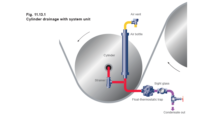
One special case of interest is the drying cylinder used in many process industries. A horizontal cylinder is supplied with steam through a rotary joint at one end, and the material being processed is in contact with the outer surface of the cylinder. Condensate is discharged through a dip pipe passing either through the same rotary joint or a similar joint at the opposite end of the cylinder.
With cylinders of appreciable size, the volume of air to be discharged at 'start-up' is large. Air collecting within the cylinder during normal operation leads to cold spots on the outer surface, and improperly processed material is produced. Automatic air venting is paramount, and must be achieved as a matter of course if good results are to be expected.
The best steam trap for this purpose is a float-thermostatic type with steam lock release, but a separate air vent is often still needed due to the large amount of air to be purged.
Experience shows an air vent and an air collecting bottle at the condensate outlet, will give an excellent result if fitted as shown in Figure 11.13.1.
Group air venting
Steam equipment designers sometimes reduce expenditure by connecting the remote points of two or more steam spaces, and fitting a single air vent, rather than using individual air vents for each steam space. Unfortunately such an arrangement is often unsuccessful. A multi-coil air heater can have each of the coils supplied from a common steam header which is fed through a single control valve. Here, the air vent will close when steam from one section reaches it. Air, present in the other sections, would simply not reach the vent to open it. Later, the steam in the air vent body condenses, and is replaced again. Again, when the incoming steam is from the coil containing the least air, the vent tends to quickly close. The air/steam mixtures in the other coils are not induced to flow towards the vent position. Group air venting is not successful, and should be avoided, in the same way as the group steam trapping of condensate drain lines.
Extra large air vents
The capacity of an air vent depends on the size of the orifice, the differential pressure across the seat, and the properties of the gas being discharged. In some instances, the steam spaces being vented are very large, as in large sterilisers and retorts in the food industry, large autoclaves, rubber curing vessels etc. The amount of air to be vented may then be so great as to require large numbers of air vents to be fitted in parallel. An alternative answer is to use a self-acting temperature control, fitted similarly to that in Figure 11.13.2.
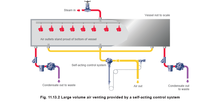
The valve must be of a pattern suitable for use on steam service. The valve is positioned by the control system, and the temperature sensor is located on the downstream side of the valve. The temperature setting is adjusted to 100°C, or just below this value. Since the pressure in the tail pipe at the temperature sensor is atmospheric, the temperature at this point would be 100°C if air-free steam had reached the sensor after flowing through the valve. At this temperature, the valve should just be closed. Any lower temperature at the sensor location means that some air is present, and the valve will be slightly opened.
Positioning the temperature sensor in this way, downstream of the valve where the line pressure is atmospheric, nullifies the effect of pressure upstream of the valve. The control system has only to close the valve when the sensor temperature reaches 100°C and open it at lower temperatures. This arrangement makes it quite practical to use air vent valves as large as the DN50, which enables large volumes of air to be discharged.
Venting air through thermostatic steam traps
Any thermostatic steam trap, such as the balanced pressure bellows or capsule, or the bimetallic type, can be used as an air vent. Clearly the operating unit should be one that reacts quickly to temperature changes, and traps incorporating bimetal strips of large dimensions are probably less suitable. But, if a thermostatic steam trap is used primarily to drain condensate, how effectively will it vent air?
Since the trap will be open at start-up when the steam is turned on, it will discharge the air being pushed towards it.
During normal running however, the trap may not be quite as effective as an air vent. As a steam trap, it will close to condensate just below saturation temperature. It follows that with a water seal present at the inlet side of the trap, air and any other non-condensables will be sealed within the process steam space for a little time by the condensate.
When the condensate at the steam trap eventually loses some of its heat, only then will the trap open and discharge both condensate and the cool air/steam mixture.
The most effective way to release air by a steam trap from a steam space is to use a float type steam trap with an inbuilt air vent. As condensate should always get to the trap, the passage of non-condensables to the integral air vent is not held up during normal operation.
It must be made clear that the automatic device which is being used to discharge air/steam mixtures, whether it be described as a steam trap or as an air vent, is best positioned above the water level in the trap. In all other cases, the addition of air vents (at positions where the air/steam mixture can reach them under all conditions) can have beneficial results out of all proportion to the extra costs involved.