Steam Traps and Steam Trapping

Contents
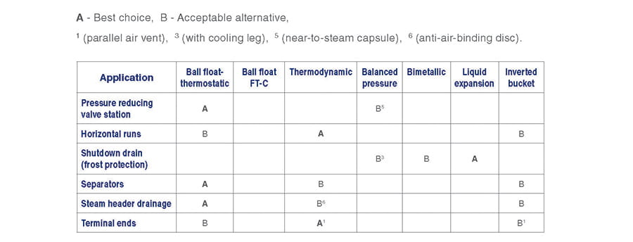
Selecting Steam Traps - Steam Mains; Tanks and Vats; Pressure Reducing Valves
Selection tables and advice on trap selection for different types of steam mains, headers and off-takes are included in this tutorial, together with process vats and pressure reducing valve stations.
Steam mains
Stream mains
Steam mains carry water droplets in suspension in the steam, as well as a layer of condensate and air on the wall of the pipe. Both the air and water must be removed for maximum plant output.
Steam traps should discharge into adequately sized condensate lines, falling towards a vented receiver. Because condensate return lines often run alongside steam mains, there is a temptation to connect into them the discharges from the traps draining the main. If the condensate returns are flooded, as they often are, severe waterhammer will result. This is undesirable if the traps are of the blast discharge type, and the practice of discharging into flooded lines should be avoided to deter waterhammer.
The condensate loads associated with mains drainage are relatively small hence a low capacity thermodynamic trap is more suitable. Thermodynamic traps are very robust and offer long life and efficient operation in exposed conditions.
Horizontal runs
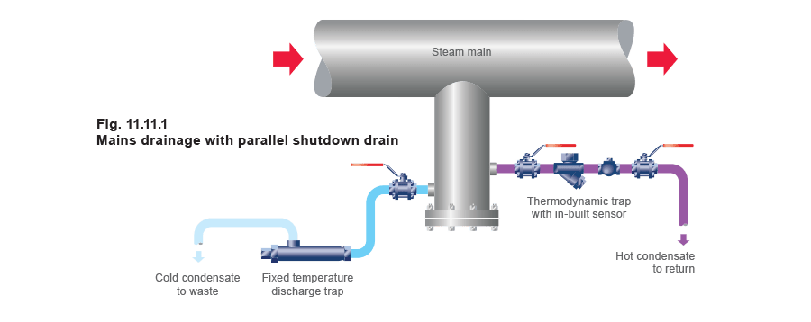
Horizontal runs must not be drained through a small pipe connection in the bottom of the pipe. Use a properly sized pocket into which fast moving condensate can fall - as shown in Figure 11.11.1.
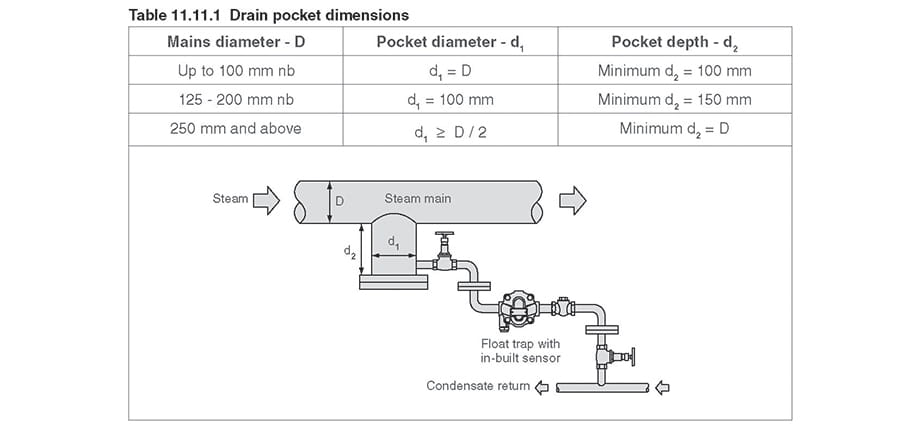
Drain pocket dimensions
Typical recommended drain pocket dimensions, relative to steam main pipe sizes are given in Table 11.11.1.
Separators
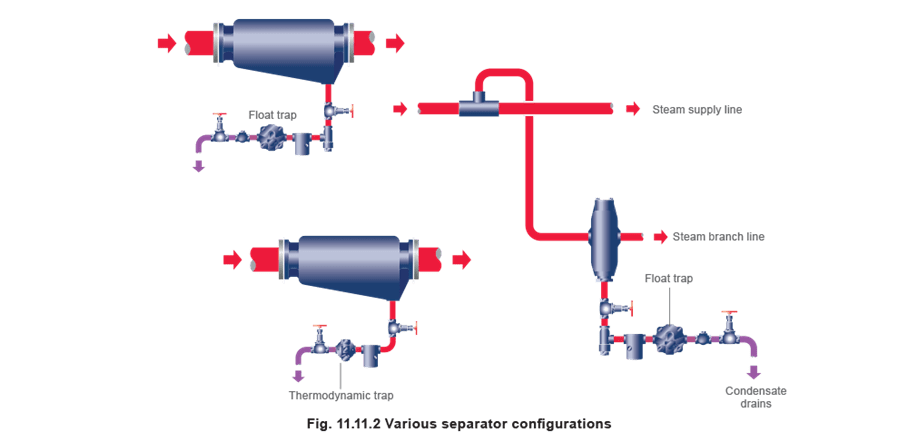
Separators are normally fitted line size. A separator will remove the suspended droplets as well as the condensate layer and provide drier steam for heating and processes (Figure 11.11.2). As it is essential to clear condensate as it forms, the first choice is a float-thermostatic trap. Alternatively, the inverted bucket trap could be used with a separate air vent as in Figure 11.11.4. The third alternative, the thermodynamic trap, is ideal for outside mains in exposed conditions, as it will not be damaged by freezing.
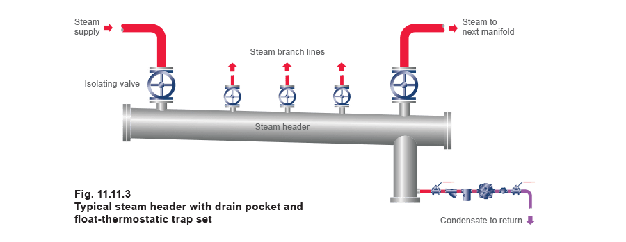
Steam header drainage
Steam headers should be drained in a similar way to steam mains, with a pocket suitably placed along the bottom of the manifold. A slight fall towards the end which houses the drain pocket assists drainage. Headers longer than 5 m may benefit from a drain pocket at either end. Float traps are best suited to handling fluctuating condensate loads. If headers situated close to boilers are susceptible to carryover, thermodynamic traps with anti-air-binding discs are good alternatives.
Note: The drain pocket should be sized as per Table 11.11.1. The distribution header diameter should be sized on a steam velocity of 10-15 m/s, for the maximum incoming steam load.
Terminal ends
Terminal or ‘dead’ ends are inherently more susceptible to waterhammer than horizontal runs because of their position in the pipework. Air will also tend to collect at these positions at start-up as steam will push any air in its path to the furthest point in the system. It is sensible therefore to position a steam trap and air vent here.
A ‘Tee’ piece, shown in Figure 11.11.4, will help to dissipate any mechanical forces caused by waterhammer, thus helping to protect the trap and vent from mechanical damage, whilst offering a simple way to install them.
The best trap for this is the thermodynamic type due to its robust design, but a good alternative is an inverted bucket should this be preferred. Both will require an air vent, for the reasons stated above.
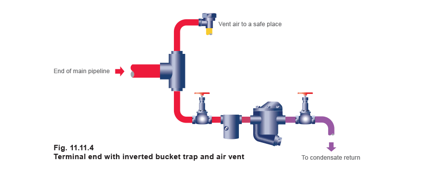
Air venting
Venting the end of the main, as shown in Figure 11.11.4, will provide quicker heating-up and faster production - further details are given in Module 11.12, ‘Air Venting Theory’. On a long main, or one which is started up daily, it may also be necessary to fit air vents at certain intermediate drain points. The discharge from an air vent should not be connected into a flooded condensate return line (as waterhammer may result), nor into a line carrying sub-cooled condensate (since this can encourage corrosion of the pipework).
Branch mains to process
Optimum heat transfer will be obtained from any process when it is fed with dry steam. The branch line should be taken from the top of the main, and where it is relatively long or convoluted, the line should be well insulated and fitted with a small separator and trap set before the plant inlet.
Figure 11.11.2, shows the arrangement where the separator is drained by a float-thermostatic trap.
Any process having a temperature controlled steam supply would benefit from having a drain trap set situated immediately before the control valve. This will drain the line of condensate when the control valve is shut, preventing waterhammer damage and erosion of the valve seat by wet steam upon opening. The ultimate benefits are to increase the working life and performance of the valve and process. Again, if there is likelihood of wet steam at the end of the branch line, it is better to fit a separator.
Tanks and Vats

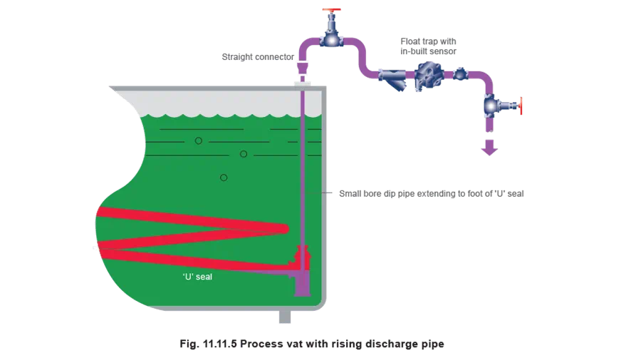
Process vats (rising discharge pipe)
Figure 11.11.5 is most important. A coil in a process liquor vat should have a fall, and finish in a ‘U’ seal if the outlet rises. The rising pipe must be of small diameter. By placing a small pipe down to the bottom of the seal, and closing the pipe at the top with a convenient coupling, steam locking is prevented. The steam trap can be a float-thermostatic, thermodynamic or a balanced pressure type. A thermodynamic trap can sometimes prove useful in the case of certain corrosive liquors if the coil leaks, because it is less affected by corrosion than the other types. Should there be fear of contamination of the condensate by the tank contents, allow the condensate to drain to waste. Any condensate from corrosive liquors should be carefully disposed of, particularly if there is a fear that the tank contents could contaminate the steam and condensate system. A vacuum breaker should be fitted on the steam inlet side of the coil if the tank content is corrosive, to remove the possibility of corrosive liquor being drawn back into the steam supply.
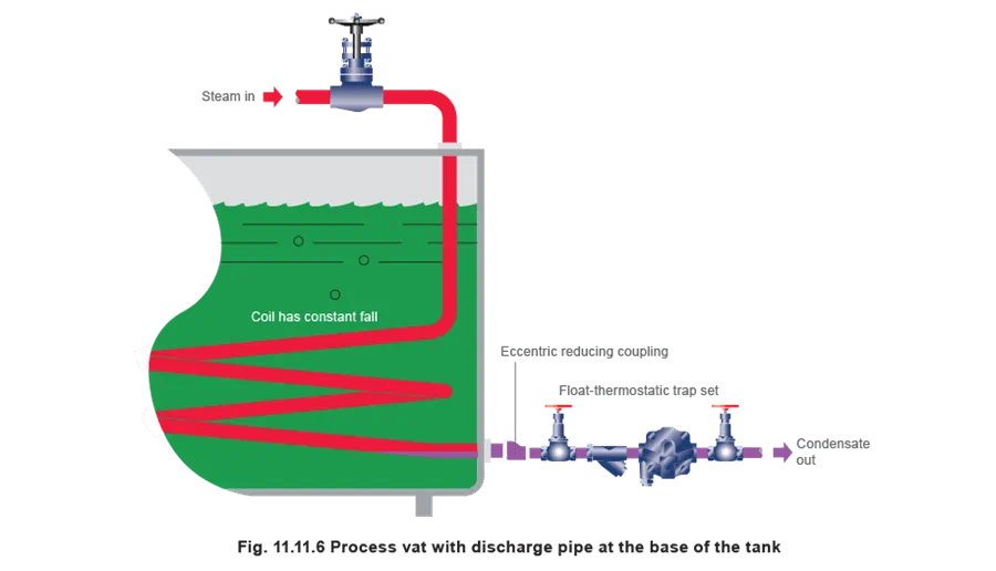
Process vats (discharge pipe at base)
If the coil has an outlet through the side of the vat, Figure 11.11.6 shows the recommended drain arrangement using a float-thermostatic trap. Thermodynamic and balanced pressure types can also be used. It is important to use an eccentric reducer on the end of a horizontal coil, not a concentric one. A concentric reducer could cause waterlogging of the bottom part of the coil, which would reduce heat transfer, and increase the risk of waterhammer.
The system will operate better if condensate from the trap is allowed to fall to a non-flooded return line or vented receiver for pumping.
Pressure Reducing Valves
Where there is a possibility that the pipework downstream of reducing valves could be shut off during normal operation, a trapping point should be provided to drain any condensate formed during this period. This keeps the downstream pipework free of water and protects the reducing valve from filling with water and 'locking-up'. Float traps discharge condensate continuously and do not disturb the pressure in the pipe when discharging.
