Steam Traps and Steam Trapping

Contents
The effect of air
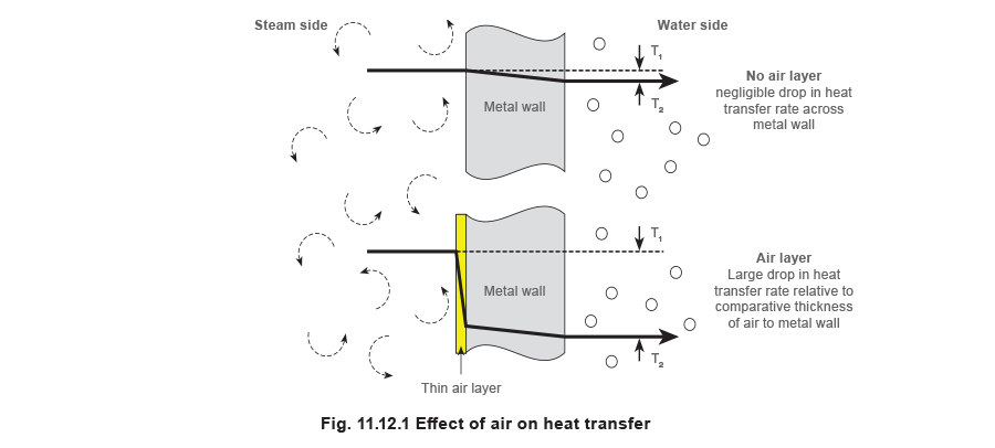
If air is mixed with steam and flows along with it, pockets of air will remain at the heat exchange surfaces where the steam condenses. Gradually, a thin layer builds up to form an insulating blanket, hindering heat transfer as shown in Figure 11.12.1. Air is widely used as an insulator because of its low conductivity (for instance, double glazing used in modern windows is simply two layers of glass with an insulating layer of air sandwiched between them). Similarly, air is used to reduce the heat loss from steam pipes. Most insulating material is made up of millions of microscopic air cells, within a matrix of fibre glass, mineral wool, or polymer-type material. The air is the insulator and the solid material simply holds it in position. Similarly, a film of air on the steam side of a heat transfer surface is resistive to the flow of heat, reducing the rate of heat transfer.
The thermal conductivity of air is 0.025 W/m °C, while the corresponding figure for water is typically 0.6 W/m °C, for iron it is about 75 W/m °C and for copper about 390 W/m °C. A film of air only 1 mm thick offers about the same resistance to heat flow as a wall of copper some 15 metres thick!
It is unlikely that the air exists as an even film inside the heat exchanger. More probably, the concentration of air is higher close to the condensing surface, and lower further away. It is convenient however, to deal with it as an homogeneous layer when trying to show its resistance to heat flow.
When air is added to steam, the heat content of a given volume of the mixture is lower than the same volume of pure steam, so the mix temperature is lowered.
Dalton’s Law of Partial Pressures states that; ‘In a mixture of steam and air, the total pressure is the sum of the partial pressure each gas would exert, when occupying the total volume on its own’.
For example, if the total pressure of a steam/air mixture at 2 bar (absolute) is made up of 3 parts steam to 1 part air by volume, then:
Partial pressure of air = ¼ x 2 bar a = 0.5 bar a
Partial pressure of steam = ¾ x 2 bar a = 1.5 bar a
Total pressure of mixture = 0.5 + 1.5 bar a = 2 bar a (1 bar g)
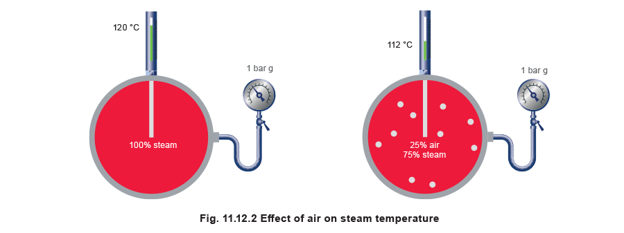
The pressure gauge would indicate a pressure of 1 bar g, inferring a corresponding temperature of 120°C to the observer. However, the partial pressure due to the amount of steam present in the mixture is only 0.5 bar g (1.5 bar a), contributing a temperature of only 112°C. Hence, the presence of air has a double effect:
- It offers a resistance to heat transfer via its layering effect.
- It reduces the temperature of the steam space thus reducing the temperature gradient across the heat transfer surface.
The overall effect is to reduce the heat transfer rate below that which may be required by a critical process, and in worst cases may even prevent a final required process temperature being reached.
In many processes, a minimum temperature is needed to achieve a chemical or physical change in a product, just as a minimum temperature is essential in a steriliser. The presence of air is particularly problematic because it will cause a pressure gauge to mislead. It follows that the temperature cannot be inferred from the pressure.
Air in the system
Air is present within steam pipes and steam equipment at start-up. Even if the system were filled with pure steam when used, the condensing steam would cause a vacuum and draw air into the pipes at shutdown.
Air can also enter the system in solution in the feedwater. At 80°C, water can dissolve about 0.6% of its volume, of air. The solubility of oxygen is roughly twice that of nitrogen, so the ‘air’ which dissolves in water contains nearly one part of oxygen to two of nitrogen rather than the one part to four parts in atmospheric air. Carbon dioxide has a higher solubility, roughly 30 times greater than oxygen.
Boiler feedwater, and condensate exposed to the atmosphere, can readily absorb these gases. When the water is heated in the boiler, the gases are released with the steam and carried into the distribution system. Unless boiler ‘make-up’ water is fully demineralised and degassed, it will often contain soluble sodium carbonate from the chemical exchange of water treatment processes. The sodium carbonate can be released to some extent in the boiler and again carbon dioxide is formed.
With higher pressure boilers, the feedwater is often passed through a deaerator before it is pumped to the boiler. The best deaerators can reduce oxygen levels to 3 parts per million (ppm) in water. This residual oxygen can then be dealt with by chemical treatment. However, such an amount of oxygen will be accompanied by about 6 ppm of nitrogen, which the chemical treatment ignores. If the boiler is of a moderate size producing 10,000 kg per hour of steam, it uses about 10,000 litres per hour of water, in turn producing 60 cm³ of nitrogen. This will cumulate over time with a significant effect on heat transfer if not removed from the system.
The best of physical and chemical treatments will still allow some untreated incondensable gas to leave the boiler with the steam. Air, frequently unsuspected, is more widespread in steam systems than believed and is the cause of both limitation of output and equipment corrosion.
Signs of air
- A gradual fall off in the output of any steam heated equipment.
- Air bubbles in the condensate.
- Corrosion.
The removal of air from steam systems is paramount. The following pages address the issue by discussing the application of air vents.
Air removal
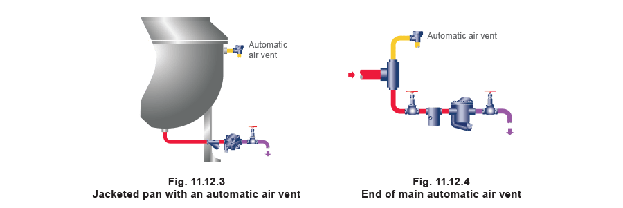
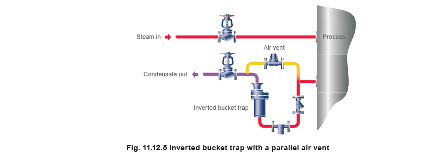
The most efficient means of air venting is with an automatic device. Air mixed with steam lowers the mix temperature. This enables a thermostatic device (based on either the balanced pressure or bimetallic principle) to vent the steam system. An air vent fitted on the steam space of a vessel (Figure 11.12.3) or at the end of a steam main (Figure 11.12.4) will open when air is present. For maximum removal of air, the discharge should be as free as possible. A pipe is often fitted to carry the discharge to a safe location, preferably not a condensate return line, which could restrict the free release of air and may also encourage corrosion.
When an air vent is fitted to bypass a steam trap (Figure 11.12.5), it will act as a steam trap after the air is vented, and may from time to time discharge condensate. In such cases it is necessary to reconnect the air vent to the condensate line after the trap.
If the condensate discharge line from a trap rises to high level, the flooded line imposes a backpressure on the trap and the air vent. The ability of the air vent to discharge air is reduced, especially at start-up. This applies equally when the air vent is incorporated within a steam trap. When the shape of the application steam space and the location of the steam inlet mean that most of the air leaves through the condensate outlet, it is preferable if discharge lines from the steam trap and air vent do not rise to high level.
The air vent location
When a coil or a vessel has a relatively small cross-section, the steam admitted to it will act like a piston, pushing the air to a point remote from the steam inlet. This 'remote point' is usually the best location for the air vent. In the case of a steam user of the shape shown in Figure 11.12.6, some of the air will pass through the condensate outlet, according to the provision made in the trap, or in a bypass, for handling air. The rest of the air might collect as indicated, forming a cold spot on the heating surface. The unit cannot warm up evenly, and distortion may be caused in some equipment, such as the beds of laundry ironers.

As an air/steam mixture is denser than pure steam at the same pressure, it is usually sufficient to provide air venting capability within the low-lying steam trap. However, the mode of operation of the trap means that condensate forms a water seal at the trap inlet sometimes preventing air from reaching the trap. There may be the need to consider an automatic air vent connected to the steam space above the level of any condensate. Often it is convenient and sufficiently effective to connect it to the top of the steam space, as in Figure 11.12.6.
However, in the case of two steam spaces of the same size and shape but with different steam inlet positions, the location of the air vent could be different. In Figure 11.12.7 and Figure 11.12.8, condensate drains from the bottom of the vessel but with the bottom steam inlet, at start-up, air would tend to be pushed to the remote point which is at the top. It may be best to locate an air vent at the top whilst a float-thermostatic steam trap will handle any residual air which has collected at the bottom of the vessel.