Steam Engineering Principles and Heat Transfer

Contents
Steam Consumption of Plant Items
The steam consumption of other common plant items, including heater batteries, calorifiers, drying cylinders, presses and tracer lines.
The examples in the following sections within this Module are a revision of previously mentioned equipment, and indicate the steam consumption of other common plant items.
Heater batteries

Most manufacturers of unit heaters and air heater batteries give the output of their equipment in kW. The condensing rate may be determined from this by dividing the equipment rating (in kW) by the enthalpy of evaporation of the steam at the operating pressure (in kJ/kg) to give a steam flowrate in kg/s.
Multiplying the result by 3 600 will give kg/h.

If the manufacturer’s figures are not available, but the following is known:
- The volumetric air flowrate.
- The temperature rise.
- The steam pressure.
Then the condensing rate can be determined by using Equation 2.12.3:

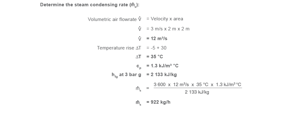
Example 2.14.1
An air heater designed to raise air temperature from -5 to 30 °C is fitted in a duct 2 m x 2 m.
The air velocity in the duct is 3 m/s, steam is supplied to the heater battery at 3 bar g, and the specific heat of air is taken as 1.3 kJ/m³ °C.
Heating calorifiers

As with air heaters, most heating calorifier manufacturers will usually provide a rating for their equipment, and the steam consumption may be determined by dividing the kW rating by the enthalpy of steam at the operating pressure to produce a result in kg/s (see Equation 2.8.1). However, calorifiers are frequently too large for the systems they serve because:
- The initial heat load calculations on the building they serve will have included numerous and over-cautious safety factors.
- The calorifier itself will have been selected from a standard range, so the first size up from the calculated load will have been selected.
- The calorifier manufacturer will have included his own safety factor on the equipment.
An estimate of the actual load at any point in time may be obtained if the flow and return temperatures and the pumping rate are known. Note however that the pressure head on the discharge side affects the throughput of the pump, and this may or may not be constant.
Example 2.14.2
4 l/s of low temperature hot water (flow/return = 82/71 °C) is pumped around a heating system.
Determine the heat output:
- Heat output = Water flowrate x specific heat of water x temperature change
- Heat output = 4 l/s x 4.19 kJ/kg °C x (82 - 71 °C)
- Heat output = 184 kW
An alternative method of estimating the load on a heating calorifier is to consider the building being heated. The calculations of heat load can be complicated by factors including:
- Air changes.
- Heat transfer rates through walls, windows and roofs.
However, a reasonable estimate may be obtained by taking the volume of the building and allowing a heating capacity of 30 W/m³. This will give the running load for an inside temperature of about 20 °C when the outside temperature is about -1 °C.
Typical flow and return temperatures for:
- Low temperature hot water (LTHW) systems are 82 °C and 71 °C (ΔT = 11 °C).
- Medium temperature hot water (MTHW) systems are 94 °C and 72 °C (ΔT = 22 °C).
Figures for high temperature hot water (HTHW) systems vary considerably, and must be checked for each individual application.
Example 2.14.3
The steam flow to a heating calorifier has been measured as 227 kg/h when the outside temperature is 7 °C and the inside temperature is 18 °C.
If the outside temperature falls to -1 °C, and the inside temperature is 19 °C, determine the approximate steam flowrate. This can be calculated by proportionality.

Hot water storage calorifiers
Hot water storage calorifiers are designed to raise the temperature of their entire contents from cold to storage temperature within a specified time period.

Typical UK values are:
- Cold water temperature 10 °C
- Hot water temperature 60 °C
Heat up time (also referred to as ‘recovery time’) = 1 hour.
The mass of water to be heated may be determined from the volume of the vessel. (For water, density ρ = 1 000 kg/m³, and specific heat (cp) = 4.19 kJ/kg °C).
Example 2.14.4
A storage calorifier comprises of a cylindrical vessel, 1.5 m diameter and 2 m high. The contents of the vessel are to be heated to 60 °C in 1 hour.
The incoming water temperature is 10 °C, and the steam pressure is 7 bar g.
Determine the steam flowrate:

Drying cylinders
Drying cylinders vary significantly in layout and application and, consequently, in steam consumption.
Apart from wide variations in size, steam pressure, and running speed, cylinders may be drained through the frame of the machines, as in textile can dryers, or by means of a blow-through system in the case of high speed paper machines. Conversely, film dryers and slow speed paper machines may use individual steam traps on each cylinder. Demand will vary from small standing losses from a cylinder drying sized cotton thread, to the heavy loads at the wet end of
a paper machine or in a film dryer.

Because of this, accurate figures can only be obtained by measurement. However, certain trusted formulae are in use, which enable steam consumption to be estimated within reasonable limits.
In the case of textile cylinder drying machines, counting the number of cylinders and measuring the circumference and width of each will lead to the total heating surface area. The two ends of each cylinder should be included and 0.75 m² per cylinder should be added to cover doll heads and frames except where individual trapping is used. The radiation loss from the machine, while standing, measured in kg of steam per hour, can be estimated by multiplying
the total area by a factor of 2.44. The running load in kg per hour will be obtained by using a factor of 8.3. (In imperial units the area will be measured in square feet and the corresponding factors will be 0.5 and 1.7 respectively). This is based on a machine drying piece goods at a rate of 64 to 73 metres per minute, (70 to 80 yards per minute), but by making allowances, it can be used for machines working under different conditions.

The factors in the equation above are empirically derived constants:
1.5 = Factor applied to cylinder dryers.
2 550 = Average water enthalpy + enthalpy of evaporation required to evaporate moisture.
1.26 = Average specific heat of material.
Drying cylinders tend to have a heavy start-up load due to the huge volume of the steam space and the mass of metal to be heated, and a factor of three times the running load should be allowed in sizing steam traps. It must also be remembered that air can cause particular difficulties, such as prolonged warming up times and uneven surface temperature. Special provision must therefore be made for venting air from the cylinders.
Presses
Presses, like drying cylinders, come in all shapes, sizes and working pressures, and are used for many purposes, such as moulding plastic powders, preparing laminates, producing car tyres (see Figure 2.14.4), and manufacturing plywood. They sometimes also incorporate a cooling cycle.
Clearly, it would be difficult to calculate steam loads with any accuracy and the only way of getting credible results is by measurement.
This type of equipment may be ‘open’, allowing a radiation loss to atmosphere, or ‘closed’, when the two heating surfaces are in effect insulated from each other by the product. Although some heat is absorbed by the product, the net result is that the steam consumption is much the same whether the plant is working or standing idle, although fluctuations will occur during opening and closing.

Steam consumption can sometimes be estimated using the basic heat transfer Equation 2.5.3:

The U values shown in Figure 2.9.1 may sometimes be used. They can give reasonable results in the case of large platen presses but are less accurate when small numbers of intricately shaped moulds are considered, mainly due to the difficulty of estimating the surface area.
A feature of this type of plant is the small steam space, and a relatively high steam load when warming up from cold. To account for this and the load fluctuations, steam traps should be sized with a factor of 2 times the running load. Temperature control can be very accurate using pilot operated direct acting reducing valves, giving a constant and consistent steam pressure corresponding to the required surface temperature. These are sized simply on the designed steam load.
Tracer lines
Pipelines carrying viscous fluids are frequently maintained at an elevated temperature by means of steam tracers. These usually consist of one or more small bore steam lines running alongside the product line, the whole being covered in insulation.
In theory, the exact calculation of steam consumption is difficult, as it depends on:
- The degree of contact between the two lines, and whether heat conducting pastes are used.
- The temperature of the product.
- The length, temperature and pressure drop along the tracer lines.
- The ambient temperature.
- Wind speed.
- The emissivity of the cladding.

In practice, it is usually safe to assume that the tracer line simply replaces radiation losses from the product line itself. On this basis, the steam
consumption of the tracer line may be taken as a running load being equal to the radiation loss from the product lines.
Table 2.14.1 provides heat losses from insulated pipes with either 50 or 100 mm of insulation.

Example 2.14.5
A 50 m long x 200 mm pipe contains a liquid product at 120 °C. The ambient temperature is 20 °C, the pipe has 50 mm of insulation, and steam is supplied at 7 bar g to the tracer(s).
Determine the steam consumption:

For jacketed lines, the heat loss may be assumed to be the same as that from a steam main which has a diameter equal to that of the jacket; also taking any insulation into account.
When sizing the steam traps, a factor of 2 times the running load should be used to cover startup conditions, but any temperature control valve can be sized to handle the design load only.
Sizing the tracer line
Example 2.14.5 calculates the steam tracer load on the basis of the heat loss from the pipe.
In practice, the tracer line will not be exactly sized to match this heat loss. Table 2.14.2 shows the useful heat output from 15 mm and 20 mm steel and copper tracer lines operating at different pressures alongside product lines at different temperatures. The Table accounts for heat losses from the tracer lines to the surrounding air through the insulation.

In Example 2.14.5, the heat loss from the pipe was 97 W/m. The tracer line has to be able to supply at least this rate of heat transfer.
Table 2.14.2 shows that, by interpolation, the useful heat output from a 15 mm steel tracer line is 33 W/m for a product temperature of 120 °C and a steam pressure of 5 bar g.
The number of tracers required to maintain the product temperature of 120 °C are therefore:

Therefore three 15 mm steel tracer lines will be required for this application as shown in Figure 2.14.9.
