Steam Engineering Principles and Heat Transfer

Contents
Entropy - Its Practical Use
Entropy can be used to understand thermodynamic applications from first principles. This tutorial gives practical examples of how this can be done.
Practical use of entropy
It can be seen from Module 2.15 that entropy can be calculated. This would be laborious in practice, consequently steam tables usually carry entropy values, based on such calculations. Specific entropy is designated the letter ‘s’ and usually appears in columns signifying specific values for saturated liquid, evaporation, and saturated steam, sf, sfg and sg respectively. These values may equally be found in charts, and both Temperature - Entropy (T - S) and Enthalpy - Entropy (H - S) charts are to be found, as mentioned in Module 2.15. Each chart has particular use in specific circumstances.
The T - S chart is often used to determine the properties of steam during its expansion through a nozzle or an orifice. The seat of a control valve would be a typical example.
To understand how a T - S chart is applied, it is worth sketching such a chart and plotting the steam properties at the start condition, reading these from the steam tables.
Example 2.16.1
Steam is expanded from 10 bar a and a dryness fraction of 0.9 to 6 bar a through a nozzle, and no heat is removed or supplied during this expansion process. Calculate the final condition of the steam at the nozzle outlet. Specific entropy values quoted are in units of kJ/kg °C.
At 10 bar a, steam tables state that for dry saturated steam:

As no heat is added or removed during the expansion, the process is described as being adiabatic and isentropic, that is, the entropy does not change. It must still be 6.141 3 kJ/kg °C at the very
moment it passes the throat of the nozzle.
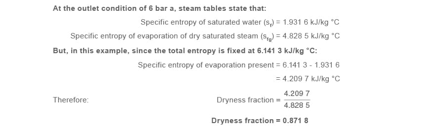
By knowing that this process is isentropic, it has been possible to calculate the dryness fraction at the outlet condition. It is now possible to consider the outlet condition in terms of specific
enthalpy (units are in kJ/kg).
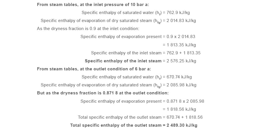
It can be seen that the specific enthalpy of the steam has dropped in passing through the nozzle from 2 576.25 to 2 489.30 kJ/kg, that is, a heat drop of 86.95 kJ/kg.
This seems to contradict the adiabatic principle, which stipulates that no energy is removed from the process. But, as seen in Module 2.15, the explanation is that the steam at 6 bar a has just
passed through the nozzle throat at high velocity, consequently it has gained kinetic energy. As energy cannot be created or destroyed, the gain in kinetic energy in the steam is at the expense
of its own heat drop.
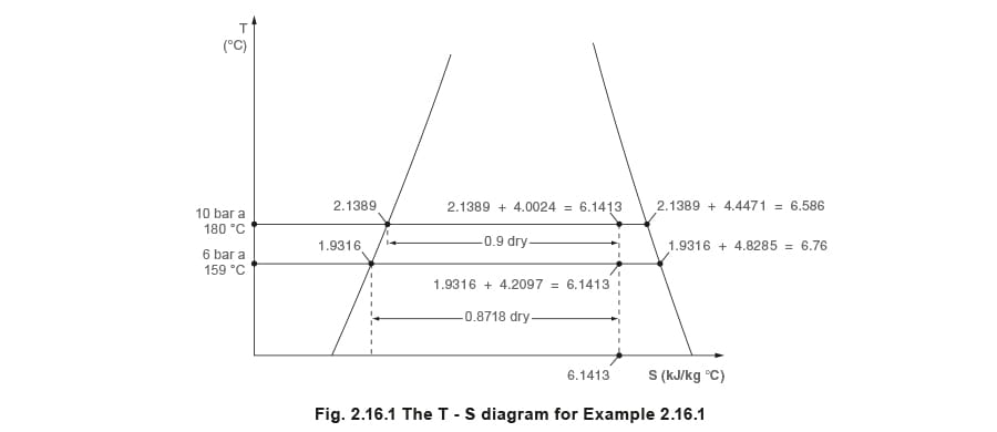
The above entropy values in Example 2.16.1 can be plotted on a T - S diagram, see Figure 2.16.1
Further investigation of kinetic energy in steam
What is the significance of being able to calculate the kinetic energy of steam? By knowing this value, it is possible to predict the steam velocity and therefore the mass flow of steam through control valves and nozzles.
Kinetic energy is proportional to mass and the square of the velocity.
It can be further shown that, when incorporating Joule’s mechanical equivalent of heat, kinetic energy can be written as Equation 2.16.1:
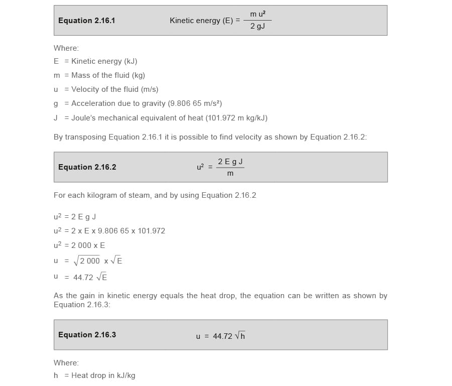
By calculating the adiabatic heat drop from the initial to the final condition, the velocity of steam can be calculated at various points along its path; especially at the throat or point of minimum pass area between the plug and seat in a control valve.
This could be used to calculate the orifice area required to pass a given amount of steam through a control valve. The pass area will be greatest when the valve is fully open. Likewise, given the valve orifice area, the maximum flowrate through the valve can be determined at the stipulated pressure drop. See Examples 2.16.2 and 2.16.3 for more details.
Example 2.16.2
Consider the steam conditions in Example 2.16.1 with steam passing through a control valve with an orifice area of 1 cm². Calculate the maximum flow of steam under these conditions.
The downstream steam is at 6 bar a, with a dryness fraction of 0.871 8.
Specific volume of dry saturated steam at 6 bar a (sg) equals 0.315 6 m³/kg.
Specific volume of saturated steam at 6 bar a and a dryness fraction of 0.871 8 equals 0.315 6 m³/kg x 0.871 8 which equates to 0.275 1 m³/kg.
The heat drop in Example 2.16.1 was 86.95 kJ/kg, consequently the velocity can be calculated using Equation 2.16.3:
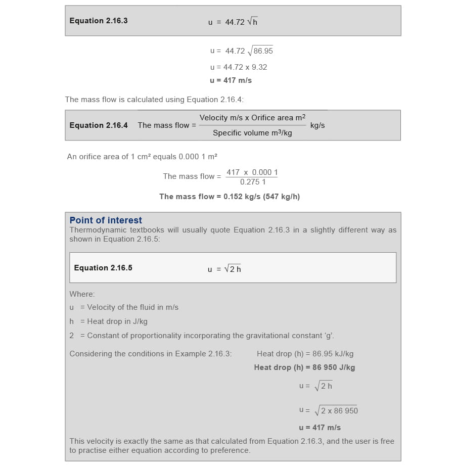
The calculations in Example 2.16.2 could be carried out for a whole series of reduced pressures, and, if done, would reveal that the flow of saturated steam through a fixed opening increases quite quickly at first as the downstream pressure is lowered.
The increases in flow become progressively smaller with equal increments of pressure drops and, with saturated steam, these increases actually become zero when the downstream pressure is 58% of the absolute upstream pressure. (If the steam is initially superheated, CPD will occur at just below 55% of the absolute upstream pressure).
This is known as the ‘critical flow’ condition and the pressure drop at this point is referred to as critical pressure drop (CPD). After this point has been reached, any further reduction of downstream pressure will not give any further increase in mass flow through the opening.
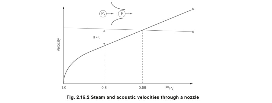
In fact if, for saturated steam, the curves of steam velocity (u) and sonic velocity (s) were drawn for a convergent nozzle (Figure 2.16.2), it would be found that the curves intersect at the critical pressure. P1 is the upstream pressure, and P is the pressure at the throat.
The explanation of this, first put forward by Professor Osborne Reynolds (1842 - 1912) of Owens College, Manchester, UK, is as follows:
Consider steam flowing through a tube or nozzle with a velocity u, and let s be the speed of sound (sonic velocity) in the steam at any given point, s being a function of the pressure and density of the steam. Then the velocity with which a disturbance such as, for example, a sudden change of
pressure P, will be transmitted back through the flowing steam will be s - u.
Referring to Figure 2.16.2, let the final pressure P at the nozzle outlet be 0.8 of its inlet pressure P1. Here, as the sonic velocity s is greater than the steam velocity u, s - u is clearly positive. Any change in the pressure P would produce a change in the rate of mass flow.
When the pressure P has been reduced to the critical value of 0.58 P1, s - u becomes zero, and any further reduction of pressure after the throat has no effect on the pressure at the throat or the rate of mass flow.
When the pressure drop across the valve seat is greater than critical pressure drop, the critical velocity at the throat can be calculated from the heat drop in the steam from the upstream condition to the critical pressure drop condition, using Equation 2.16.5.
Control valves
The relationship between velocity and mass flow through a restriction such as the orifice in a control valve is sometimes misunderstood.
Pressure drop greater than critical pressure drop
It is worth reiterating that, if the pressure drop across the valve is equal to or greater than critical pressure drop, the mass flow through the throat of the restriction is a maximum and the steam will travel at the speed of sound (sonic velocity) in the throat. In other words, the critical velocity is equal to the local sonic velocity, as described above.
For any control valve operating under critical pressure drop conditions, at any reduction in throat area caused by the valve moving closer to its seat, this constant velocity will mean that the mass flow is simultaneously reduced in direct proportion to the size of the valve orifice.
Pressure drop less than critical pressure drop
For a control valve operating such that the downstream pressure is greater than the critical pressure (critical pressure drop is not reached), the velocity through the valve opening will depend on the application.
Pressure reducing valves
If the valve is a pressure reducing valve, (its function is to achieve a constant downstream pressure for varying mass flowrates) then, the heat drop remains constant whatever the steam load. This means that the velocity through the valve opening remains constant whatever the steam load and valve opening. Constant upstream steam conditions are assumed.
It can be seen from Equation 2.16.4 that, under these conditions, if velocity and specific volume are constant, the mass flowrate through the orifice is directly proportional to the orifice area.

Temperature control valves
In the case of a control valve supplying steam to a heat exchanger, the valve is required to reduce the mass flow as the heat load falls. The downstream steam pressure will then fall with the heat load, consequently the pressure drop and heat drop across the valve will increase.
Thus, the velocity through the valve must increase as the valve closes.
In this case, Equation 2.16.4 shows that, as the valve closes, a reduction in mass flow is not directly proportional to the valve orifice, but is also modified by the steam velocity and its specific volume.
Example 2.16.3
Find the critical velocity of the steam at the throat of the control valve for Example 2.16.2, where the initial condition of the steam is 10 bar a and 90% dry, and assuming the downstream pressure is lowered to 3 bar a.

The critical velocity occurs at the speed of sound, consequently 430 m/s is the sonic velocity for the Example 2.16.3.
Noise in control valves
If the pressure in the outlet of the valve body is lower than the critical pressure, the heat drop at a point immediately after the throat will be greater than at the throat. As velocity is directly related to heat drop, the steam velocity will increase after the steam passes the throat of the restriction, and supersonic velocities can occur in this region.
In a control valve, steam, after exiting the throat, is suddenly confronted with a huge increase in space in the valve outlet, and the steam expands suddenly. The kinetic energy gained by the steam in passing through the throat is converted back into heat; the velocity falls to a value similar to that on the upstream side of the valve, and the pressure stabilises in the valve outlet and connecting pipework.
For the reasons mentioned above, valves operating at and greater than critical pressure drop will incur sonic and supersonic velocities, which will tend to produce noise. As noise is a form of vibration, high levels of noise will not only cause environmental problems, but may actually cause the valve to fail. This can sometimes have an important bearing when selecting valves that are expected to operate under critical flow conditions.
It can be seen from previous text that the velocity of steam through control valve orifices will depend on the application of the valve and the pressure drop across it at any one time.
Reducing noise in control valves
There are some practical ways to deal with the effects of noise in control valves.
Perhaps the simplest way to overcome this problem is to reduce the working pressure across the valve. For instance, where there is a need to reduce pressure, by reducing pressure with two valves instead of one, both valves can share the total heat drop, and the potential for noise in the pressure reducing station can be reduced considerably.
Another way to reduce the potential for noise is by increasing the size of the valve body (but retaining the correct orifice size) to help ensure that the supersonic velocity will have dissipated by the time the flow impinges upon the valve body wall.
In cases where the potential for noise is extreme, valves fitted with a noise attenuator trim may need to be used.
Steam velocities in control valve orifices will reach, typically, 500 m/s. Water droplets in the steam will travel at some slightly lower speed through a valve orifice, but, being incompressible, these droplets will tend to erode the valve and its seat as they squeeze between the two.
It is always sensible to ensure that steam valves are protected from wet steam by fitting separators or by providing adequate line drainage upstream of them.
Summing up of Modules 2.15 and 2.16
The T - S diagram, shown in Figure 2.16.1, and reproduced below in Figure 2.16.3, shows clearly that the steam becomes wetter during an isentropic expansion (0.9 at 10 bar a to 0.871 8 at 6 bar a) in Example 2.16.1.
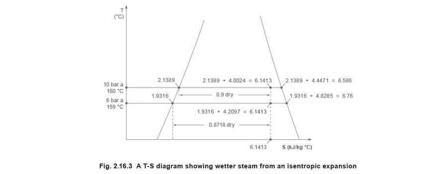
At first, this seems strange to those who are used to steam getting drier or becoming superheated during an expansion, as happens when steam passes through, for example, a pressure reducing valve.
The point is that, during an adiabatic expansion, the steam is accelerating up to high speed in passing through a restriction, and gaining kinetic energy. To provide this energy, a little of the steam condenses (if saturated steam), (if superheated, drops in temperature and may condense) providing heat for conversion into kinetic energy.
If the steam is flowing through a control valve, or a pressure reducing valve, then somewhere downstream of the valve’s seat, the steam is slowed down to something near its initial velocity.
The kinetic energy is destroyed, and must reappear as heat energy that dries out or superheats the steam depending on the conditions.
The T - S diagram is not at all convenient for showing this effect, but the Mollier diagram (the H - S diagram) can do so quite clearly.
The Mollier diagram can depict both an isenthalpic expansion as experienced by a control valve, (see Figure 2.15.6) by moving horizontally across the graph to a lower pressure; and an isentropic expansion as experienced by steam passing through a nozzle, (see Figure 2.15.7) by moving horizontally down to a lower pressure. In the former, the steam is usually either dried or superheated, in the latter, the steam gets wetter.
This perhaps begs the question, ‘How does the steam know if it is to behave in an isenthalpic or isentropic fashion?’ Clearly, as the steam accelerates and rushes through the narrowest part of the restriction (the throat of a nozzle, or the adjustable gap between the valve and seat in a control valve) it must behave the same in either case.
The difference is that the steam issuing from a nozzle will next meet a turbine wheel and gladly give up its kinetic energy to turn the turbine. In fact, a nozzle could be thought of as a device to convert heat energy into kinetic energy for this very purpose.
In a control valve, instead of doing such work, the steam simply slows down in the valve outlet passages and its connecting pipework, when the kinetic energy appears as heat energy, and unwittingly goes on its way to give up this heat at a lower pressure.
It can be seen that both the T - S diagram and H - S diagram have their uses, but neither would have been possible had the concept of entropy not been utilised.