Condensate Removal

Contents
The Stall Chart - Varying Flow Secondary - Constant Inlet Temperature - Constant Outlet Temperature
- Varying Flow Secondary
- Constant Inlet Temperature
- Constant Outlet Temperature
Varying flowrate with constant inlet/outlet temperature
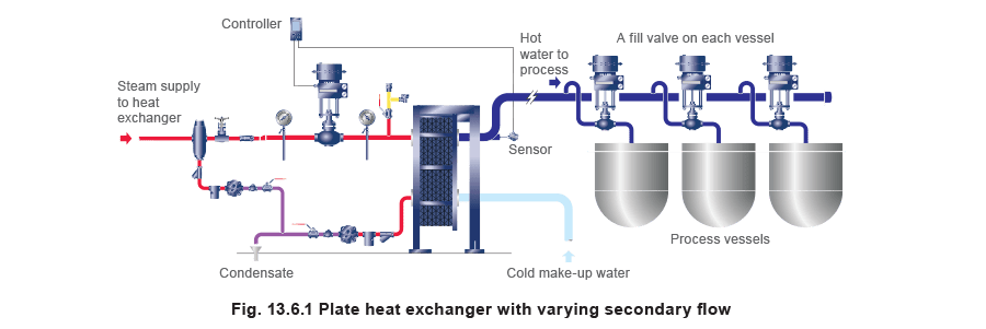
Not all heat exchangers are required to operate with a constant secondary flow. Typical applications might include the provision of hot water to batch processes such as tanks and vats. The supply of hot water to each tank is controlled either by means of an on-off ball valve or a modulating globe valve; there is no recirculation of water back to the heat exchanger. Cold make-up water is simply heated as per the hot water demand, as depicted in Figure 13.6.1. A modulating control valve on the steam supply to the heat exchanger regulates the temperature of the hot water being drawn off. The cold make-up water might be supplied from a pressurised main, and its temperature may alter seasonally. Its lowest probable temperature should be considered when considering the stall condition.
The stall chart can also be used in these types of installations, but the construction method for shell and tube heat exchangers is slightly different to that used for constant secondary flow. This method is described below.
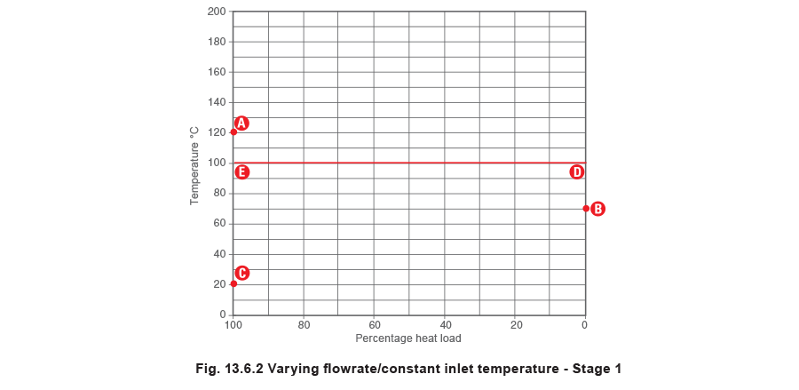
The first part of this method is very similar to that shown in Example 13.5.1. With reference to Figure 13.6.2, the steam temperature in the heat exchanger under full-load conditions (Point A) should be marked on the left vertical axis. The desired secondary fluid outlet temperature should then be marked on the right vertical axis (Point B).
The secondary fluid inlet temperature (Point C) should also be marked on the left vertical axis.
The horizontal line representing the system backpressure must also be marked on this chart. This temperature should be marked on the right vertical axis at point D, with a straight line connecting it to the same temperature on the left vertical axis at point E.
With reference to Figure 13.6.3, the secondary load line BC should be drawn connecting points B and C. A horizontal line should then be drawn from where BC crosses the 50% load ordinate, to the right axis. This represents the mean secondary fluid temperature, and is shown as point F.
The mean secondary fluid temperature point F should then be connected by a diagonal straight line to the steam temperature point A in the heat exchanger under full-load, creating the line AF.
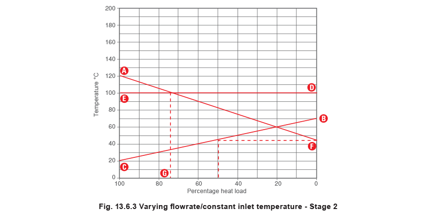
The backpressure line DE will either intersect the steam line AF, or be above point A on the chart. The point of intersection between the lines AF and DE marks the stall point, where the steam pressure and the backpressure are the same. A vertical line may be dropped down from the stall point, to indicate when the stall condition occurs.
The point at which this vertical line crosses the bottom horizontal axis (Point G) should mark the percentage load. As in the previous example, if the line DE is above the point A, stall occurs under all load conditions.
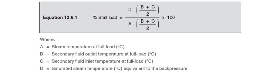
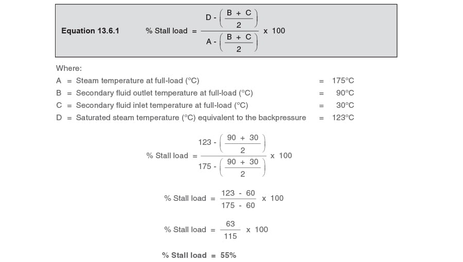
The percentage stall load can also be calculated using Equation 13.6.1:
The minimum steam temperature
It should be noted that the lowest operating steam temperature equals the set point temperature at point B. This occurs at 70°C in the stall chart, Figure 13.6.4, and is represented by point H on the steam line AF.
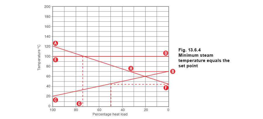
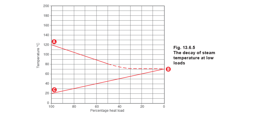
In practice, as the heat load decreases, and the steam temperature approaches the secondary control temperature at point H, changes in steam temperature occur slowly rather than the rapid step change suggested at point H in Figure 13.6.4. The steam temperature will tend to fall in a similar way to that shown in Figure 13.6.5. It is difficult and unnecessary to draw this line on a stall chart, whereas Figure 13.6.4 is practical and easy to use.
Referring to Figure 13.6.4, it can be seen in this example that the steam temperature at any load less than 37% is 70°C. In truth, the gradual fall in steam temperature is more like that depicted in Figure 13.6.5, but the difference is so small as to be insignificant with regard to selecting and sizing the trapping device.
Example 13.6.1
The steam pressure inside a shell and tube heat exchanger with a varying secondary flowrate at full-load is 8 bar g, the pressure in the condensate line is 0.5 bar g, and there is a lift of 7 metres after the trap. At full-load, the secondary fluid enters the heat exchanger at 30°C and leaves the heat exchanger at 90°C with a flowrate of 3.64 L / s.
What is the percentage load at stall, and what is the secondary flowrate through the heat exchanger at stall?
The saturation temperature of the steam at 8 bar g is 175°C. Therefore the steam temperature in the heat exchanger at full-load is 175°C. This should then be plotted as point A in Figure 13.6.6.
The secondary fluid outlet temperature of 90°C should be plotted as point B, while the secondary fluid inlet temperature of 30°C should be plotted as point C.
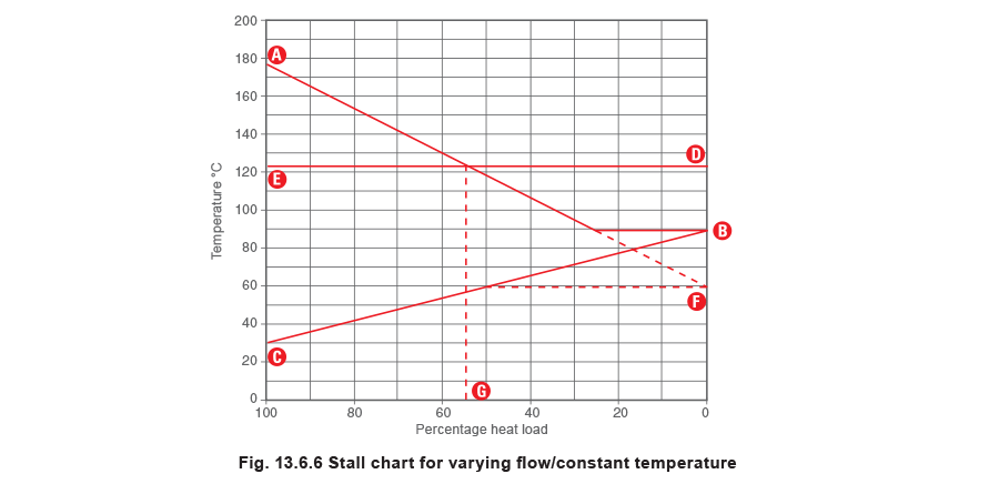
The lift in the condensate line of 7 m creates a differential pressure of 0.7 bar, in addition to the 0.5 bar g pressure in the condensate line. Therefore, the total system backpressure is 1.2 bar g. As the saturation temperature of steam at 1.2 bar g is 123°C, the horizontal line DE representing the backpressure is drawn at this temperature in Figure 13.6.6.
In this example the percentage load (Point G) is approximately 55%. This means that the secondary liquid flowrate must reduce to 55% of the maximum flowrate for stall to occur, that is, 55% of 3.64 L / s = 2 L / s. This can be verified mathmatically by using Equation 13.6.1.
Most heat exchanger applications will either be varying flowrate or varying temperature as described above and in the previous Modules in Block 13.
There may, however, also be instances where both the flowrate and the inlet temperature of the secondary fluid vary. In these examples it becomes more difficult to determine their combined effect by interpretation of the stall chart. Systems such as these can be analysed by comparing the results from both methods shown above and using the worst case.