Condensate Removal

Contents
Heat Exchangers And Stall
This Block discusses the removal of condensate from heat exchange equipment supplied by saturated steam and fitted with:
The primary side of the heat exchanger will be referred to as the ‘steam space’, and the steam trapping device will be referred to as the ’trap’. The ‘trap’ can be a ‘steam trap’, a ‘pump trap’, or a ‘steam trap and pump’ fitted in combination.
On these installations, a control sensor monitors the temperature of the outgoing heated fluid in the secondary circuit. The control valve endeavours to maintain a temperature determined by the controller, regardless of variations in heat load. The valve achieves this by opening or closing to alter the flowrate of steam, thereby varying the steam space pressure.
The discharge from the steam trap may be subject to a lift and/or pressure in the condensate line, or may fall to an open end where it is subjected only to atmospheric pressure. This Block will refer to condensate pressure as ‘backpressure’.
The heat exchange equipment can be almost anything that meets the above criteria. Examples include:
- Shell and tube heat exchangers.
- Plate heat exchangers.
- Air heating coils or batteries in ductwork.
- Pipe runs or pipe coils in process equipment, tanks, vats etc.
For brevity, this Block will refer to all such devices as ‘heat exchangers’ or ‘heaters’, and the passage of fluid being heated by the heat exchanger will be referred to as passing through the ‘secondary’ side of the heat exchanger.
The performance of steam heat exchangers is often reduced due to condensate flooding the steam space and waterlogging. The two main causes of waterlogging are:
- Fitting the wrong type of trap.
- Stall.
Important note
Some systems aim to achieve control of temperature by positively encouraging partial flooding of the steam space of the heat exchanger. In these cases, the modulating action of the control valve at the condensate outlet varies the condensate level in the steam space. This changes the area of heating surface exposed to steam, and the effect is to change the heat transfer rate so as to control the secondary outlet temperature.
With systems of this type, it is important that the heat exchangers be designed and manufactured specifically to withstand the effects of flooding. Where this is not done, the presence of condensate in the heat exchanger will have an adverse effect on operating performance and will reduce service life.
This method of control can have certain benefits if the system is designed correctly. One is that the condensate sub-cools in the heat exchanger before it is discharged. This can considerably reduce the amount of flash steam in the condensate pipework, which may improve the performance of the condensate system and also reduce heat losses.
The main operational disadvantage is that systems of this type are slow to respond to variations in heat load.
What is meant by stall?
Stall is the reduction or the cessation of condensate flow from the heat exchanger, and occurs when the pressure in the heat exchanger is equal to, or less than, the total backpressure imposed on the steam trap.
Lower than expected pressure in a heat exchanger may occur as a result of any of the following circumstances:
• The secondary fluid inlet temperature rising as a result of a falling heat load.
• The secondary fluid flowrate falling as a result of a falling heat load.
• The secondary fluid outlet temperature falling due to a lowering of the set point.
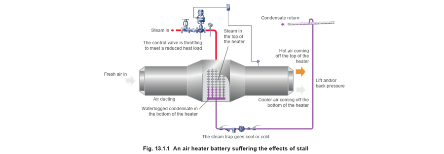
As the control valve reduces the steam pressure to meet a falling heat load, the lack of differential pressure across the steam trap causes condensate to waterlog the steam space, as shown in Figure 13.1.1.
Due to applied safety factors and because heat exchangers are sold in pre-determined sizes, they often have more heating area than required. This has the effect of increasing the heat transfer capability of the exchanger above that required. It also means that the operating steam pressure will be lower than in a comparable heat exchanger perfectly sized for the same duty. The result is that less steam pressure is available to push out the condensate than may be expected. The steam pressure in the heat exchanger is important because it influences the stall condition, which in turn affects trap selection.
Before any trap selection and sizing can take place, it is necessary to determine whether or not stall will occur, and if it does, to what degree. If this is not done, it is likely that the heat exchanger will suffer from waterlogging for some or all of its operating life. This, when it occurs, may not be immediately recognised by the observer or operator, as operating performance might not be reduced in an oversized heat exchanger. However, waterlogging can have severe financial consequences, short and long term, unless the heat exchanger is designed to operate this way.
Short-term problems
Consider an oversized heater battery operating as a frost coil and fitted with the wrong type (or size) of trap, as in Figure 13.1.1.
In this example, the frost coil is preheating chilled air before it passes on to the main heater battery. Though the frost coil is fulfilling its thermal expectations (because it is oversized for the duty), it will do so with the bottom half of its coils waterlogged. Incoming cold air approaching 0°C (typically flowing at 3 m/s) passing over the coils can easily cause the water in them to freeze. This results in having to repair or replace the heater battery, either causing inconvenience or unexpected outlay.
Waterlogging and freezing will not arise if the application is correctly designed.
Long-term problems
Traps that are undersized will sometimes show no immediate adverse effects on heater performance if the heater is oversized.
Ironically, the wrong type of trap fitted to a heat exchanger can often exaggerate a superficial improvement elsewhere in the condensate system. For instance, a thermostatic or fixed orifice fitted to any heat exchanger will hold back condensate so that it sub-cools below the steam saturation temperature. This will have the effect of reducing flash steam from any natural outlet such as a condensate receiver vent. The casual observer can interpret this as a way to save energy and can easily be tempted to fit these devices. Unfortunately, the situation is not as straightforward as it seems. The reality is that holding back condensate until it sub-cools implies waterlogging to some degree. Condensate that continually floods the steam space will cause corrosion with costly results. The service life of the heat exchanger is reduced, and the overall lifetime costs of the installation will increase.
The effects suffered by a waterlogged heat exchanger depend upon the circumstances of the particular installation.
The symptoms and effects of stall are itemised later in this Module.
How does stall occur?
To understand stall it is necessary to appreciate that saturated steam is a condensing vapour, which gives up its heat as it condenses to water. This condensation always occurs at a constant temperature when the pressure in the steam space remains constant.
For example, saturated steam at atmospheric pressure has a temperature of 100°C and will also condense back into water at 100°C, whereas at a gauge pressure of 1 bar, saturated steam has a temperature of 120°C and will condense back into water at 120°C. Steam can also exist inside heat exchangers at below atmospheric pressure i.e. steam at 0.5 bar below atmospheric pressure has a temperature of about 82°C, and will also condense back to water at 82°C. The pressure and temperature relationship of saturated steam is entirely predictable and is documented in steam tables.
Basic heat exchanger theory states that the higher the steam temperature above that of the secondary fluid being heated, the greater the potential heat transfer rate. To vary the transfer of heat from condensing steam, the temperature (and thus the pressure) of the steam in the steam space is varied.
For example, if a heat exchanger uses steam at 160°C at maximum load, and the load is reduced by 50%, steam at a lower temperature is required. To achieve this, the steam pressure must be reduced, and, in many cases, becomes less than the backpressure.
Example:
A heat exchanger running at full-load uses saturated steam at 1 bar g (120°C) to heat water from 40°C to 60°C. Full-load therefore occurs when the water temperature rises by 20°C, and the mean water temperature is:

The difference between the steam temperature and the mean water temperature is termed the Arithmetic Mean Temperature Difference or AMTD, and the heat transfer rate is proportional to this. The full-load AMTD in this example is 120°C - 50°C = 70°C.
Consider the situation where the process load falls to 2/3 load.
At full-load, the water temperature rise is 20°C.
If the load falls to 2/3 full-load, and the outlet water temperature remains constant at 60°C, this means that the temperature rise must be 2/3 of 20°C
Therefore:
At 2/3 load, temperature rise = 2/3 of 20°C = 13.3°C and the inlet temperature = 60°C - 13.3°C = 46.7°C
Consequently at 2/3 load, the return water temperature will have risen to 46.7°C, and so the mean water temperature is now:

At 2/3 load, the heat transfer needed will be 2/3 of that at full-load, and equally the AMTD will be 2/3 of that at full-load, i.e.

It follows that the steam temperature at 2/3 load has to be the mean water temperature at 2/3 load plus the AMTD at 2/3 load, i.e.

As the temperature of saturated steam at atmospheric pressure is 100°C, this means that the pressure in the steam space is now atmospheric. Consequently, there is no steam pressure available in the steam space to push the condensate through a steam trap. Even if the condensate line fell to an open-ended steam trap, the condensate might not drain out of the exchanger. The condensate will ‘back-up’ the drain line and waterlog the heat exchanger unless proper precautions are taken.
If condensate backs up into the exchanger, the surface area available to condense steam is reduced, the heat flow drops and the temperature of the outgoing heated water begins to fall. When the temperature sensor detects this, the controller opens the control valve a little more and the inflow of steam increases. This raises the pressure in the steam space above atmospheric (in this case) and soon becomes high enough to push condensate through the trap. The condensate level falls, but now the steam space pressure is higher than the atmospheric pressure needed to just heat the water to 60°C. The water temperature then climbs. When the sensor detects this, the controller closes down the control valve. The steam space pressure falls to atmospheric - and the flooding begins again.
The result is a continual cycling of the water temperature above and below 60°C. If the secondary medium were other than water this could, in many cases, affect its quality.
What are the symptoms and effects of stall?
One or more of the following symptoms may be evident:
In summary:
- Cold or cool steam trap.
- Hunting control valve.
- Fluctuating outlet temperature.
- Stratified heater temperatures.
- Waterhammer.
- Reduced heat output.
- Reduced product quality.
- Corroding heat exchangers.
- Leaking heat exchangers.
- Failing heat exchangers.
In detail:
- The steam trap goes cold, or is noticeably cooler than the temperature of the steam pipe inlet to the heat exchanger.
- The control valve is prone to ‘hunting’, i.e. it cycles regularly somewhere between its open and closed positions.
- The temperature of the secondary fluid flowing from the heat exchanger is less accurate than is expected or required.
- There is stratification of temperature on the output side of the heat exchanger. This will be more apparent on heater batteries and unit heaters.
For example, it is almost certain to be detectable on the air heater battery depicted in Figure 13.1.1. The design is such that the face of the heat exchanger surface is usually accessible, often via an access panel or door in the side of the ducting. If stall is happening, the top of the battery closest to the steam inlet will be very hot, whereas lower down, it will be much cooler or even cold, and the trap will be cool or cold. The temperature of the air flowing through the top of the battery will be noticeably higher than that flowing through the bottom.
- The heat exchanger makes crackling, banging or thumping noises either continuously or intermittently. Sometimes these noises are associated with severe waterhammer that can cause physical damage to the heat exchanger and any equipment fitted to it. The hot steam condensing into the waterlogged condensate causes the waterhammer and resulting noises, especially when the waterlogging level varies with changes in load.
- In process applications, the result of one or more of the above symptoms may be poor or unreliable product quality.
- Increased corrosion. The waterlogged condensate cools to temperatures much lower than the steam temperature at the inlet to the steam space. Carbon dioxide and oxygen dissolve much more readily into cooler water.
- Carbon dioxide is a common by-product of incorrect boiler water treatment and is carried over into the heat exchanger with the steam. When it dissolves into water it forms carbonic acid, which causes corrosion.
Oxygen is present in raw water, and if not completely removed by the water treatment process, it too will get carried over with the steam. Its presence in water, especially cool water in which it will readily dissolve, also aggravates corrosion.
Corrosion rates are greatly accelerated when both gases are present.
The degree of corrosion will depend upon the heat exchanger material. Copper, carbon steel, and stainless steel will each be affected differently.
Mechanical stress.
The hot steam in the top of the steam space will cause the heat exchanger to expand there, while the cool water in the bottom of the steam space has the reverse effect. This uneven expansion/contraction can cause mechanical stress to the heat exchanger structure, notably to the soldered, brazed, welded or expanded joints in ‘plate’ and ‘shell and tube’ heat exchangers, and air heater batteries. The most common result is leakage of steam to the surroundings in the former, or into the secondary airflow in the latter. The stress tends to be worse if the waterlogging level continually varies, especially if it varies quickly. The level of waterlogging will vary as the load changes, and as a result; the control valve and steam trap will struggle to achieve stable control.
It should be said that a properly engineered plate heat exchanger with gasket joints suitably designed for steam will be very resilient to such stress.
The ultimate effect of stall is increased maintenance and shorter service life of the heat exchanger and associated equipment. This increases overall running costs.
Do all heat exchangers suffer from stall?
No. The conditions may be such that there will always be sufficient positive pressure upstream of the steam trap to clear the condensate so stall cannot occur.
As a general rule, the higher the secondary temperature above 100°C, and the more stable the running load, (especially if near to the maximum output of the heat exchanger), the less likely for stall to occur. However, each application is unique and will require individual consideration. The only ways to determine the dynamics of the installation are to either plot the application temperatures on a chart or to perform a mathematical calculation. This is explained in Module 13.2, ‘Condensate Removal from Heat Exchangers’.
Some applications can appear to operate with partial waterlogging, and show little effect of waterhammer. These tend to be steady load applications, or where the load changes only slightly and very slowly, and/or applications that employ very robust heat exchange equipment.
One such example would be large bore corrosion resistant heating coils inside tanks correctly arranged to have a positive fall towards the trapping points.
Even in applications of this type, if the installation is designed or corrected to eliminate stall, improved operation, improved reliability, and reduced lifetime costs are virtually guaranteed.