Control Applications

Contents
Pressure Control Applications
There are many good reasons for reducing (and sometimes maintaining) steam pressure. This tutorial details common applications for direct operating, pilot operated, pneumatic, electric and electropneumatic pressure control systems, including the advantages and disadvantages of each different control method.
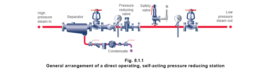
Direct operating, self-acting pressure reducing valve – bellows type
Description
With this self-acting type of pressure controller, the downstream (control) pressure is balanced (via a bellows) against a spring force.
Advantages:
- Inexpensive.
- Small.
- Easy to install
- Very robust, giving long life with minimum maintenance.
- Tolerant of imperfect steam conditions.
- Self-acting principle means that no external power is required.
Disadvantages:
- Proportional only control.
- Proportional band is 30% to 40% of the upstream pressure.
- Wide proportional band means that maximum flow is only achieved when the downstream pressure has dropped considerably. This means that the reduced pressure will vary depending on flowrate.
- Limited in size
- Limited flowrate.
- Variation in upstream pressure will result in variation in downstream pressure.
Applications:
Non-critical, moderate load applications with constant running flowrates, for example:
- Small jacketed pans.
- Tracer lines.
- Ironers.
- Small tanks.
- Acid baths.
- Small storage calorifiers.
- Unit heaters.
- Small heater batteries.
- OEM equipment.
Points to note:
- Different versions for steam, compressed air, and water.
- Soft seat versions may be available for use on gases.
- A wide range of body materials means that particular standards, applications and preferences can be satisfied.
- A wide proportional band means care is needed if the safety valve needs to be set close to the working pressure.
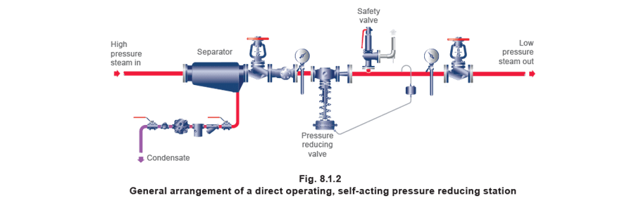
Direct operating, self-acting pressure reducing valve – diaphragm type
With this self-acting type of pressure controller, the downstream (control) pressure is balanced (via a diaphragm) against a spring force.
Advantages:
- Very robust.
- Tolerant to wet and dirty steam.
- Available in large sizes, so high flowrates are possible.
- Easy to set and adjust.
- Simple design means easy maintenance.
- Self-acting principle means that no external power is required.
- Able to handle pressure drops of 50:1 in small sizes, and 10:1 in large sizes.
Disadvantage:
- Large proportional band means that close control of downstream pressure is improbable with large changes in load.
- Relatively high purchase cost, but lifetime cost is low.
- Bulky.
Application:
- Distribution mains.
- Boiler houses.
Points to note:
- Because the diaphragm is subject to fairly low temperature limitations, a water seal is required on steam applications. This adds to the cost slightly.
- Because of the large proportional band, this type of valve is better suited to reducing steam pressure to plant areas rather than individual plant items.
- A bellows sealed stem ensures zero maintenance and zero emissions.
- Although wide proportional band provides stability, care is needed if a safety valve needs to be set close to the apparatus working pressure.
- Suitable for liquid applications.
- More expensive than a pilot operated valve, but less expensive than a pneumatic control system.
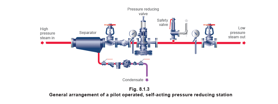
Pilot operated, self-acting pressure reducing valve
Description
These have a more complex self-acting design, and operate by sensing the downstream pressure via a pilot valve, which in turn operates the main valve.
The effect is a very narrow proportional band, typically less than 200 kPa.
This, together with low hysterisis, results in very tight and repeatable control of pressure, even with widely varying flowrates.
Advantages:
- Accurate and consistent pressure control, even at high and variable flowrates.
- A variety of pilot valves may be used on one main valve. Pilot valve options include electrical override, multi-pilot for a choice of control pressures, a surplussing option and remote control, as well as different temperature/pressure control combinations.
- Self-acting principle means that no external power is required.
- Tolerant of varying upstream pressure.
Disadvantages:
- More expensive than bellows operated direct acting controls.
- Small clearances mean that steam must be clean and dry to ensure longevity, but this can be achieved by fitting a strainer and separator before the pressure reducing valve.
Application:
- A system which requires accurate and consistent pressure control, and installations which have variable and medium flowrates. For example: autoclaves, highly rated plant such as heat exchangers and calorifiers.
- A system where installation space is limited.
Points to note:
- Installation must include a strainer and separator.
- Size for size, pilot operated valves are more expensive than bellows type self-acting controls, but cheaper than diaphragm type self-acting controls.
- Size for size, they have higher capacity than bellows type self-acting controls, but less than diaphragm type self-acting controls.
- Can be installed before temperature control valves to maintain a constant upstream pressure, and hence stabilise control.
- Not suitable for liquid applications.
- Do not use if the plant is subject to vibration, or other equipment is causing pulses in flow.
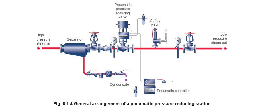
Pressure reduction – pneumatic
Description
These control systems may include:
- P + I + D functions to improve accuracy under varying load conditions.
- Set point(s), which may be remotely adjusted.
Advantages:
- Very accurate and flexible.
- No limit on valve size within the limits of the valve range.
- Acceptable 50:1 flow rangeability (typically for a globe control valve).
- Suitable for hazardous environments.
- No electrical supply required.
- Fast operation means they respond well to rapid changes in demand.
- Very powerful actuation being able to cope with high differential pressures across the valve.
Disadvantages:
- More expensive than self-acting controls.
- More complex than self-acting controls.
- Not directly programmable.
Application:
A system which requires accurate and consistent pressure control, and installations which have variable and high flowrates and/or variable or high upstream pressure. For example: autoclaves, highly rated plant such as large heat exchangers and calorifiers.
Points to note:
- A clean, dry air supply is required.
- A skilled workforce is required to install the equipment, and instrument personnel are required for calibration and commissioning.
- The control is ‘stand-alone’, and cannot communicate with PLCs (Programmable Logic Controllers).
- The failure mode can be important. For example, a spring-to-close on air failure is normal on steam systems.
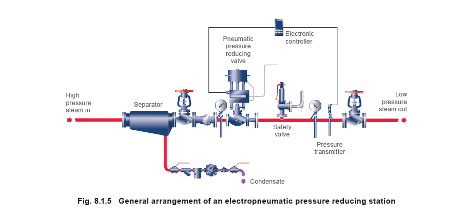
Pressure reduction – electropneumatic
Description
These control systems may include:
- P + I + D functions to improve accuracy under varying load conditions.
- Set point(s) which may be remotely adjusted, with the possibility of ramps between set points.
Advantages:
- Very accurate and flexible.
- Remote adjustment and read-out.
- No limit on valve size within the limits of the valve range.
- Acceptable 50:1 flow rangeability (typically for a globe control valve).
- Fast operation – rapid response to changes in demand.
- Very powerful actuation being able to cope with high differential pressures across the valve.
Disadvantages:
- More expensive than self-acting or pneumatic controls.
- More complex than self-acting or pneumatic controls.
- Electrical control signal required. Costly for hazardous areas.
Application:
A system which requires accurate and consistent pressure control, and installations which have variable and high flowrates and/or variable or high upstream pressure, including autoclaves, highly rated plant such as large heat exchangers and calorifiers, and main plant pressure reducing stations.
Points to note:
- A clean, dry air supply is required.
- A skilled workforce is required to install the equipment, and instrument personnel are required for calibration and commissioning.
- Can be part of a sophisticated control system involving PLCs, chart recorders and SCADA systems.
- Always consider the failure mode, for example, spring-to-close on air failure is normal on steam systems.
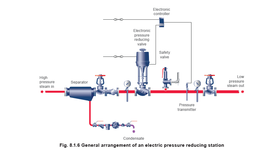
Pressure reduction – electric
Description
These control systems may include:
- P + I + D functions to improve accuracy under varying load conditions.
- Set point(s), which may be remotely adjusted.
Advantages:
- Both controller and valve actuator can communicate with a PLC.
- No compressed air supply is required.
Disadvantages:
- If a spring return actuator is required, the available shut-off pressure may be limited.
- Relatively slow actuator speed, so only suitable for applications where the load changes slowly.
Application:
- Slow opening/warm-up systems with a ramp and dwell controller.
- Pressure control of large autoclaves.
- Pressure reduction supplying large steam distribution systems.
Points to note:
- Safety: If electrical power is lost the valve position cannot change unless a spring return actuator is used.
- Spring return actuators are expensive and bulky, with limited shut-off capability.
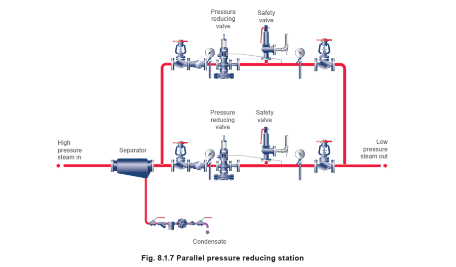
Pressure reduction (other possibilities) – Parallel pressure reducing stations
Description
Pressure reducing stations may be configured as shown below for one of two reasons:
- The valves are serving a critical application for which downtime is unacceptable. The equipment is operated on a ‘one in operation, one on stand-by’ basis to cover for breakdown and maintenance situations
- The turndown ratio between the maximum and minimum flowrates is very high. The equipment is operated on a pressure sequence principle with one valve set at the ideal downstream pressure, and the other at a slightly lower pressure. When demand is at a maximum, both valves operate; when flow is reduced, the valve set at the lower pressure shuts off first, leaving the second valve to control.
Points to note:
The valves selected for this type of application will require narrow proportional bands (such as pilot operated pressure reducing valves or electropneumatic control systems) to avoid the downstream pressure dropping too much at high flow rates.
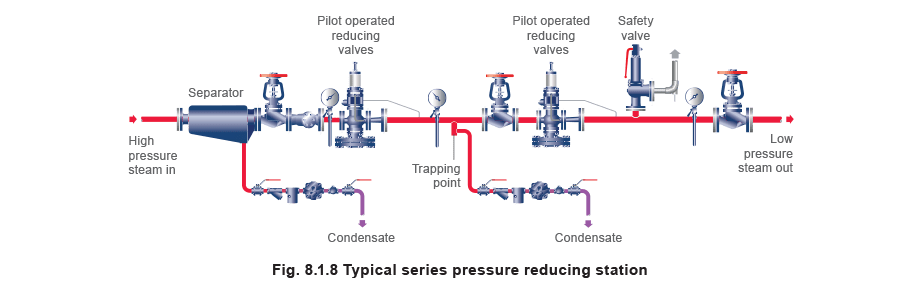
Pressure reduction (other possibilities) – Series pressure reducing stations
A pressure reducing station may be configured in this manner if the ratio between the upstream and downstream pressure is very high, and the control systems selected have a low turndown ability. 10:1 is recommended as a practical maximum pressure ratio for this type of reducing valve.
Consider the need to drop pressure from 25 bar g to 1 bar g. The primary reducing valve might reduce pressure from 25 bar g to 5 bar g, which constitutes a pressure ratio of 5:1. The secondary reducing valve would drop pressure from 5 bar g to 1 bar g, also 5:1. Both valves in series provide a pressure ratio of 25:1.
It is important to check the allowable pressure turndown ratio on the selected reducing valve, this may be 10:1 on a self-acting valve, but can be much higher on electrically or pneumatically operated valves. Be aware that high pressure drops might have a tendency to create high noise levels. Refer to Module 6.4 for further details.
The trapping point between the two reducing valves (Figure 8.1.8) is to stop a build up of condensate under no-load conditions. If this were not fitted, radiation losses would cause condensate to fill the connecting pipe, which would cause waterhammer the next time the load increased.
Desuperheaters
Desuperheating is the process by which superheated steam is either restored to its saturated state, or its superheated temperature is reduced. Further coverage of desuperheaters is given in Block 15.
The system in Figure 8.1.9 illustrates an arrangement of a pressure reducing station with a direct contact type pipeline desuperheater.
In its basic form, good quality water (typically condensate) is directed into the superheated steam flow, removing heat from the steam, causing a drop in the steam temperature.
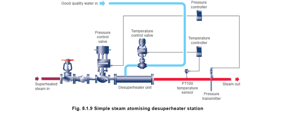
It is impractical to reduce the steam temperature to its saturated value, as the control system is unable to differentiate between saturated steam and wet steam at the same temperature.
Because of this, the temperature is always controlled at a value higher than the relevant saturation temperature, usually at 5°C to 10°C above saturation.
For most applications, the basic system as shown in Figure 8.1.9 will work well. As the downstream pressure is maintained at a constant value by the pressure control loop, the set value on the temperature controller does not need to vary; it simply needs to be set at a temperature slightly above the corresponding saturation temperature.
However, sometimes a more complex control system is required, and is shown in Figure 8.1.10. Should there be a transient change in the superheated steam supply pressure, or a change in the water supply temperature, the required water/steam flow ratio will also need to change.
A change in the water/steam flow ratio will also be required if the downstream pressure changes, as is sometimes the case with certain industrial processes.
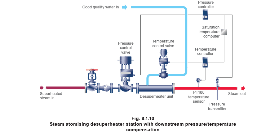
The system shown in Figure 8.1.10 works by having the pressure controller set at the required downstream pressure and operating the steam pressure control valve accordingly.
The 4-20 mA signal from the pressure transmitter is relayed to the pressure controller and the saturation temperature computer, from which the computer continuously calculates the saturation temperature for the downstream pressure, and transmits a 4-20 mA output signal to the temperature controller in relation to this temperature.
The temperature controller is configured to accept the 4-20 mA signal from the computer to determine its set point at 5°C to 10°C above saturation. In this way, if the downstream pressure varies due to any of the reasons mentioned above, the temperature set point will also automatically vary. This will maintain the correct water/steam ratio under all load or downstream pressure conditions.
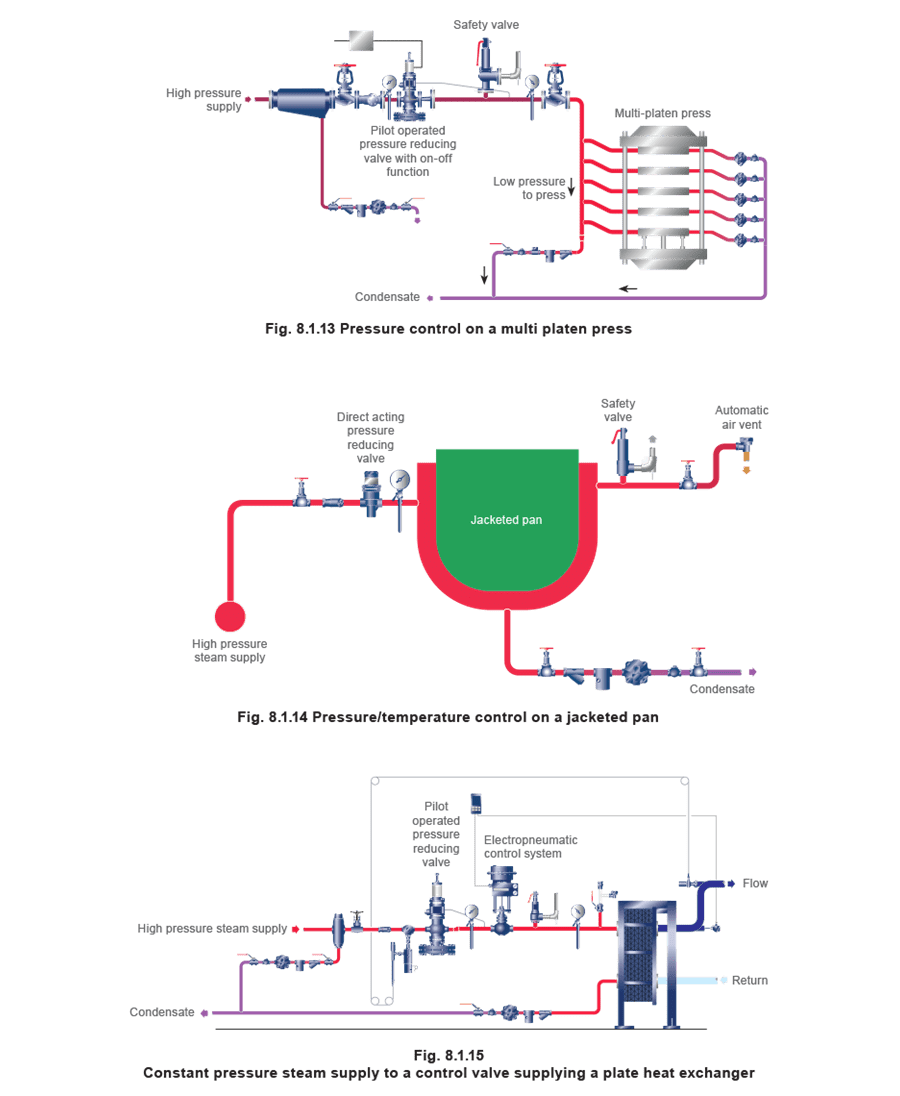
Controlling pressure to control temperature
Description
These are applications which utilise the predictable relationship between saturated steam pressure and its temperature.
Advantages:
- The pressure sensor may be located in the steam space, or close to the control valve rather than in the process medium itself. This is an advantage where it is difficult to measure the process temperature.
- This arrangement can be used to control a number of different elements from a single point.
Disadvantage:
- Control is ‘open loop’, in that the sensor is not measuring the actual product temperature.
Applications:
- Autoclaves and sterilisers
- Presses and calenders
- Constant pressure plant, for example, jacketed pans, unit heaters, and steam-jacketed pipes.
Points to note:
- Good air venting is essential (refer to Module 11.12 for further details)
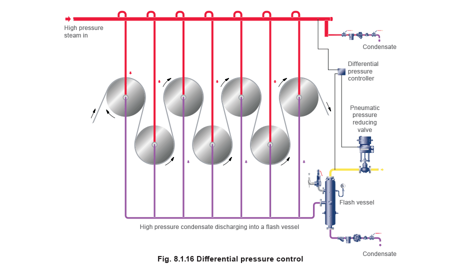
Differential pressure control
Description
In these applications the control valve will open and close to maintain a set differential pressure between two points.
Advantages:
- A constant differential steam pressure is maintained in the system.
- The differential pressure ensures that condensate is actively purged from the heat exchange system. This is particularly important where accumulated condensate could act as a heat barrier, and create a temperature gradient across the heat transfer surface. This temperature gradient could, in turn, result in a distorted or poorly heated product.
- Different operating temperatures can be achieved.
Disadvantage:
- A complex system is required if efficiency is to be maintained. This might involve flash vessels and/or thermo-compressors, as well as downstream applications which use the lower pressure pass-out steam.
Application:
- Blow-through drying rolls in a paper mill.
Points to note:
A special controller or differential pressure transmitter is required to accept two inputs; one from the primary steam supply and the other from the flash vessel. In this way, the pressure differential between the flash vessel and the primary steam supply is maintained under all load conditions.
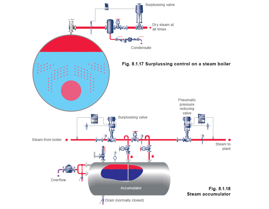
Surplussing control
Description
The objective is to maintain the pressure upstream of the control valve. Surplussing valves are discussed in further detail in Module 7.3, ’Self-acting pressure controls and applications’.
Application:
- Boilers on plants where the load can change by a large proportion over a very short period. The sudden reduction in boiler pressure may result in increased turbulence and rapid flashing of the boiler water, and large quantities of water being carried over into the pipework system.
- Accumulators where surplus boiler output is used to heat a mass of water under pressure. This stored energy is then released when the boiler has insufficient capacity.
Points to note:
- Minimum pressure drop is usually required over the fully open control valve; this may mean a ‘line size’ valve is needed.
- Not all self-acting controls are suitable for this application and it is important to consult the manufacturer before use.
Cascade control-Limiting pressure and temperature with one valve
Description
Where it is necessary to control two variables with one valve it is necessary to employ two separate controllers and sensors. It is always the case that the control valve accepts its control signal from the slave controller.
The slave controller is configured to accept two input signals, and its set point will change (within defined limits) depending on the electrical output signal from the master controller.
This form of control is very important where the pressure to the apparatus must be limited, despite the heat demand.
Application:
The steam heated plate heat exchanger shown in Figure 8.1.19 is heating water circulating in a secondary system. The heat exchanger has a maximum working pressure, consequently this is limited to that value in the slave controller.
In order to control the secondary water temperature, a master controller and temperature transmitter monitors the heat exchanger outflow temperature and sends a 4-20 mA signal to the slave controller, which is used to vary the slave set point, between pre-determined limits.
Points to note:
- An adequate pressure margin must exist between the set pressure of the safety valve and the pressure limitation imposed by the controller.
- The safety valve must not be used as a device to limit pressure in the heat exchanger; it must only be used as a safety device.

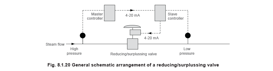
Cascade control – Combined pressure reduction and surplussing with one valve
Description
The objective is to reduce steam pressure but not at the expense of overloading the available supply capacity.
Application:
The upstream pipework is a high-pressure distribution pipe possibly from a distribution manifold or steam boiler supplying plant of a non-essential nature (Figure 8.1.20). Should the demand be higher than the supply capacity, the valve closes and throttles the steam flow, maintaining the pressure in the upstream pipework.
The master controller is set at the normal expected supply pressure. If the master detects a drop in upstream pressure below its set value (due to an increase in demand) it reduces the set point in the slave controller, in proportion to pre-determined limits.
The slave closes the valve until the steam demand falls to allow the upstream pressure to re-establish to the required value. When this is achieved, the set point of the slave controller is set at its original value.
Typical settings
The output from the master controller is direct acting, that is, when the upstream pressure is at or above its proportional band, the master’s output signal is maximum at 20 mA; when at the bottom of, or below the proportional band, the control signal is minimum at 4 mA.
When the control signal is 20 mA, the slave set point is the required downstream pressure; when the signal is 4 mA, the slave set point is at a pre-determined minimum.
Consider the ‘normal’ upstream pressure to be 10 bar g, and the maximum allowable downstream pressure to be 5 bar g. The minimum allowable upstream pressure is 8.5 bar g, which means that if this pressure is reached the valve is fully shut. The minimum reduced pressure is set at 4.6 bar g.
These conditions are recorded in Table 8.1.1

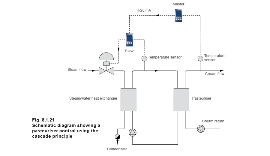
Cascade control – Limiting and controlling temperature with one valve
Description
The main objective is to limit and regulate the temperature to a particular process, where steam is the available heat source but it cannot be used directly to heat the final product for operational reasons.
Application:
A typical application is a dairy cream pasteuriser requiring a pasteurisation temperature of 50°C. Because of the low control temperature, if steam were applied directly to the pasteurisation heat exchanger, it is possible that the relatively large amount of heat in the steam would make control difficult, causing the system temperatures to oscillate, overheating and spoiling the cream.
To overcome this problem, the system in Figure 8.1.21 shows two heat exchangers. The pasteuriser is heated by hot water supplied from the primary steam heated heat exchanger.
However, even with this arrangement, if only the master controller operated the valve, a time lag would be introduced into the system, and poor control might again be the result.
Two controllers are therefore used, working in cascade, each receiving a 4-20 mA signal from their respective temperature transmitters.
The slave controller is used to control the final temperature of the product within clearly defined limits (perhaps between 49°C and 51°C). These values are altered by the master controller relative to the product temperature such that, if the product temperature increases, the slave set point reduces in proportion.