Safety Valves

Contents
Alternative Plant Protection Devices and Terminology
Other methods of relieving excess pressure explained; plus a useful terminology section.
Alternative Plant Protection Devices and Terminology
Although safety valves are by far the most common devices used for plant protection in steam systems, there are several other devices available to protect plant from overpressure conditions.
Whilst some of them can be used in place of a safety valve, most have their own unique applications and indeed some devices, such as the bursting disc, may be used to complement the safety valve.
- Weighted pallet - This is the simplest type of overpressure protection device, and it is on lowpressure tanks and condensers, for pressure relief, vacuum relief or both.
A weight is applied to the top of a disc, keeping it closed until the pressure acting on the underside of the pallet equals the weight. Due to the large weights required to keep a pallet closed, this type of valve is designed for low pressure applications below 0.1 bar. For higher set pressures,
the weight required would be prohibitive and dangerous if oscillation of the pallet occurred at valve opening.
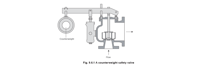
- Counterweight safety valve - Although these have been largely superseded by spring-loaded safety valves, they are still sometimes used for low-pressure applications. The closing force of the safety valve is provided by a weight rather than a spring. As the closing force is provided by a weight, it will remain constant and once the set pressure is reached, the safety valve will open fully.
- Supplementary loaded safety valve - A supplementary loaded safety valve consists of a conventional safety valve provided with an additional sealing force that is released once the set pressure is reached. One of the main concerns with this type of device is ensuring that the load is suitably released when the set pressure is reached. The EN ISO 4126 standard states that even in the event of the release mechanism failing, the valve must attain its certified discharge capacity within 115% of the set pressure.
Supplementary loaded safety valves tend only to be used where any leakage of the fluid below set pressure is unacceptable, or on very high pressure systems where maintaining a tight shutoff is otherwise difficult.
- Controlled safety pressure relief systems (CSPRS) - These are electric or electropneumatic systems, which are not self-acting. When an overpressure situation is detected, a control device acts to correct the situation.

Non-reclosing pressure relief devices
Non-reclosing devices are those which are designed to remain open after operation. A manual means of resetting is usually provided.
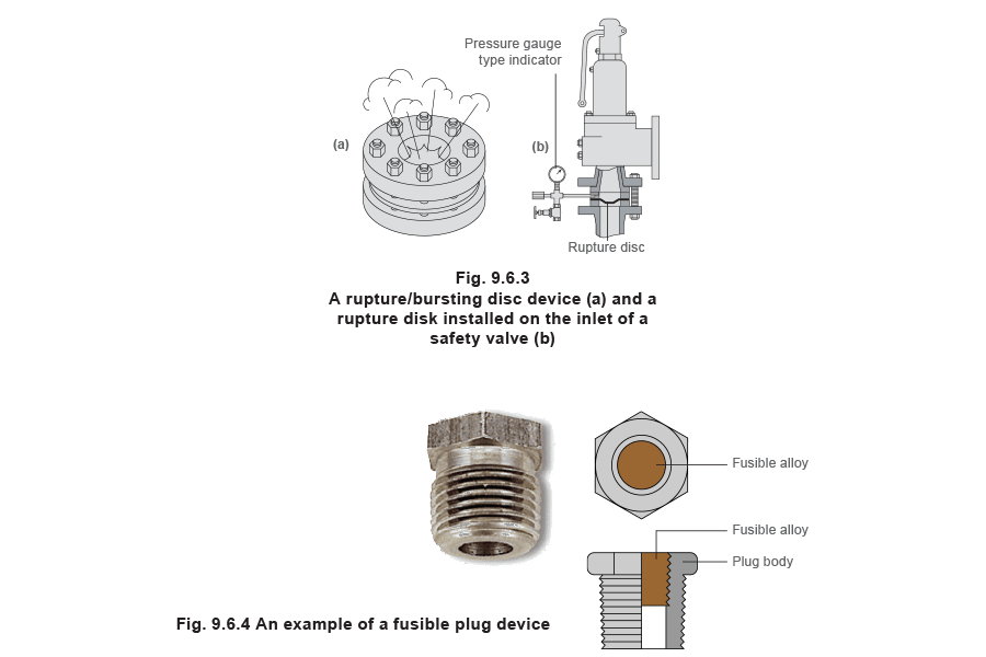
- Bursting or rupture discs - This consists of an elastomeric membrane or thin metal disk that will burst at a set pressure, relieving any overpressure. Although they can be used by themselves, on many applications, they are used in conjunction with a safety valve.
A rupture disc can be installed either on the inlet or outlet side of the safety valve. If installed on the inlet, it isolates the contained media from the safety valve. When there is an overpressure situation; the rupture disc bursts allowing the fluid to flow into the safety valve, which will then subsequently lift. This arrangement is used to protect the internals of the safety valve from corrosive fluids.
Alternatively, if the safety valve discharges into a manifold containing corrosive media, a rupture disc can be installed on the safety valve outlet, preventing any of the fluid from the manifold contacting the internals of the safety valve in normal use.
Rupture discs can also be installed alongside a safety valve as a secondary relief device.
Rupture discs are leak tight and low cost, but they require replacing after each operation. Most rupture disc installations contain a mechanism to indicate when the disc has ruptured and that it needs to be replaced. Typically, a pressure gauge is used (see Figure 9.6.3b).
Explosion panels or explosion rupture discs are similar to rupture discs but are designed for use at higher rates of pressure rise, and for larger capacities.
- Fusible plug devices - These consist of a plug with a lower melting point than the maximum operating temperature of the system that it is to protect. In old steam locomotives, this type of device was used to dump the boiler water onto the fire if overtemperature occurred.
- Breaking or shear pin devices - A breaking pin device is a non-reclosing pressure relief device actuated by inlet static pressure and designed to function by the breakage of a load carrying section of a pin, which supports a pressure-containing member. The force of overpressure forces the pin to buckle and the valve to open. The valve can then be reseated after the pressure is removed and a new pin can be installed. These devices are usually installed on low-pressure applications and large gas distribution systems. They have limited process applications.
Terminology
The following definitions are taken from DIN 3320 but it should be noted that many of the terms and associated definitions used are universal and appear in many other standards. Where commonly used terms are not defined in DIN 3320 then ASME/ANSI PTC25.3 has been used as the source of reference. This list is not exhaustive and is intended as a guide only; it should not be used in place of the relevant current issue standard:
Operating pressure (working pressure) is the gauge pressure existing at normal operating conditions within the system to be protected.
Set pressure is the gauge pressure at which under operating conditions direct loaded safety valves commence to lift.
Test pressure is the gauge pressure at which under test stand conditions (atmosphericbackpressure) direct loaded safety valves commence to lift.
Opening pressure is the gauge pressure at which the lift is sufficient to discharge the predetermined flowing capacity. It is equal to the set pressure plus opening pressure difference.
Reseating pressure is the gauge pressure at which the direct loaded safety valve is re-closed.
Built-up backpressure is the gauge pressure built up at the outlet side by blowing.
Superimposed backpressure is the gauge pressure on the outlet side of the closed valve.
Backpressure is the gauge pressure built up on the outlet side during blowing (built-up backpressure + superimposed backpressure).
Accumulation is the increase in pressure over the maximum allowable working gauge pressure of the system to be protected.
Opening pressure difference is the pressure rise over the set pressure necessary for a liftsuitable to permit the predetermined flowing capacity.
Reseating pressure difference is the difference between set pressure and reseating pressure.
Functional pressure difference is the sum of opening pressure difference and reseating pressure difference.
Operating pressure difference is the pressure difference between set pressure and operating pressure.
Lift is the travel of the disc away from the closed position.
Commencement of lift (opening) is the first measurable movement of the disc or the perception of discharge noise.
Flow area is the cross sectional area upstream or downstream of the body seat calculated from the minimum diameter which is used to calculate the flow capacity without any deduction for obstructions.
Flow diameter is the minimum geometrical diameter upstream or downstream of the body seat.
Nominal size designation of a safety valve is the nominal size of the inlet.
Theoretical flowing capacity is the calculated mass flow from an orifice having a cross sectional area equal to the flow area of the safety valve without regard to flow losses of the valve.
Actual flowing capacity is the flowing capacity determined by measurement.
Certified flowing capacity is actual flowing capacity reduced by 10%.
Coefficient of discharge is the ratio of actual to the theoretical discharge capacity.
Certified coefficient of discharge is the coefficient of discharge reduced by 10% (also known as derated coefficient of discharge).
The following terms are not defined in DIN 3320 and are taken from ASME/ANSI PTC25.3:
Blowdown (reseating pressure difference) - difference between actual popping pressure and actual reseating pressure, usually expressed as a percentage of set pressure or in pressure units.
Cold differential test pressure the pressure at which a valve is set on a test rig using a test fluid at ambient temperature. This test pressure includes corrections for service conditions e.g.backpressure or high temperatures.
Flow rating pressure is the inlet static pressure at which the relieving capacity of a pressure relief device is measured.
Leak test pressure is the specified inlet static pressure at which a quantitative seat leakage test is performed in accordance with a standard procedure.
Measured relieving capacity is the relieving capacity of a pressure relief device measured at the flow rating pressure.
Rated relieving capacity is that portion of the measured relieving capacity permitted by the applicable code or regulation to be used as a basis for the application of a pressure relieving device.
Overpressure is a pressure increase over the set pressure of a pressure relief valve, usually expressed as a percentage of set pressure.
Popping pressure is the value of increasing static inlet pressure of a pressure relief valve at which there is a measurable lift, or at which the discharge becomes continuous as determined by seeing, feeling or hearing.
Relieving pressure is set pressure plus overpressure.
Simmer is the pressure zone between the set pressure and popping pressure.
Maximum operating pressure is the maximum pressure expected during system operation.
Maximum allowable working pressure (MAWP) is the maximum gauge pressure permissible at the top of a completed vessel in its operating position for a designated temperature.
Maximum allowable accumulated pressure (MAAP) is the maximum allowable working pressure plus the accumulation as established by reference to the applicable codes for operating or fire contingencies.