Control Hardware - Self-acting Actuation

Contents
Self-acting Temperature Controls
This tutorial gives a basic introduction to what self-acting temperature control systems are and how they operate. The various different types of valves and controllers are briefly discussed along with typical applications for steam and water systems.
What are self-acting temperature controls and how do they operate?
There are two main forms of self-acting temperature control available on the market: Liquid filled systems and vapour tension systems.
Self-acting temperature controls are self-powered, without the need for electricity or compressed air.
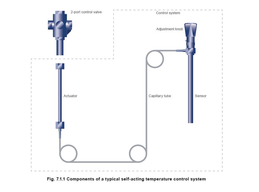
The control system is a single-piece unit comprising a sensor, capillary tubing and an actuator.
This is then connected to the appropriate control valve, as shown in Figure 7.1.1.
The self-acting principle
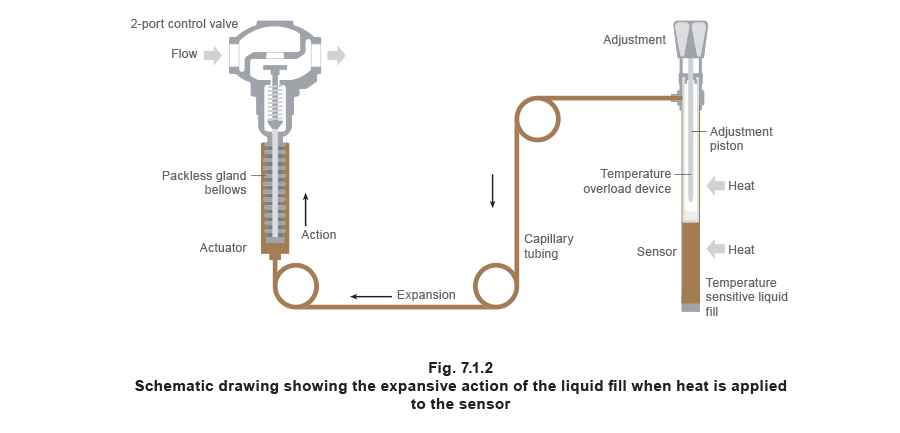
If a temperature sensitive fluid is heated, it will expand. If it is cooled, it will contract. In the case of a self-acting temperature control, the temperature sensitive fluid fill in the sensor and capillary will expand with a rise in temperature (see Figure 7.1.2).
The force created by this expansion (or contraction in the case of less heat being applied to the sensor) is transferred via the capillary to the actuator, thereby opening or closing the control valve, and in turn controlling the flow of fluid through the control valve. The hydraulic fluid remains as a liquid.
There is a linear relationship between the temperature change at the sensor and the amount of movement at the actuator. Thus, the same amount of movement can be obtained for each equal unit rise or fall in temperature. This means that a self-acting temperature control system gives ‘proportional control’; the full range of the proportional band acting above or below the set point depending on whether the application is heating or cooling. For example, if the proportional band of a self-acting heating control system were 5°C, and the set point were 70°C, then the valve would be fully closed at 70°C and fully open at 65°C. With a cooling control set at 70°C, the valve would be fully open at 70°C, and fully closed at 65°C.
The proportional band varies according to the size of the valve, larger valves having larger P-bands. Should a valve be too large for the application, the only real issue is that the stability of the system will be compromised; if the valve orifice is larger than it should be, a small change in the controlled condition (perhaps the secondary flow temperature of a heating calorifier) allows too large a change in the steam flow. The result is that the system might operate in an on-off fashion, rather than a modulating kind.
To lower the set temperature
The adjustment knob is turned clockwise to insert the piston further into the sensor. This effectively reduces the amount of space for the liquid fill, which means that the valve is closed at a lower temperature. The set temperature will therefore be lower. On control systems with dial-type adjustments, the same effect will be achieved (typically) by using a screwdriver to turn the adjustment screw clockwise.
To raise the set temperature
The adjustment knob is turned anticlockwise to decrease the length of the piston inserted in the sensor. This increases the amount of space for the liquid fill, which means that a higher temperature will be needed to cause the fill to expand sufficiently to close the control valve. The set temperature will therefore be higher.
Again, typically for a dial-type adjustment, a screwdriver is used to turn the adjustment screw anticlockwise.
Protection against high temperatures
In the event of a temperature overrun above the set temperature (possible causes of which might be a leaking control valve, incorrect adjustment, or a separate additional heat source); a series of disc springs housed inside the piston will absorb the excess expansion of the fill. This will prevent the control system from rupturing. When the temperature overrun has ceased, the disc springs will return to their original position and the control system will function as normal. Overrun is typically 30°C to 50°C above the set temperature, according to the control type.
Vapour tension systems
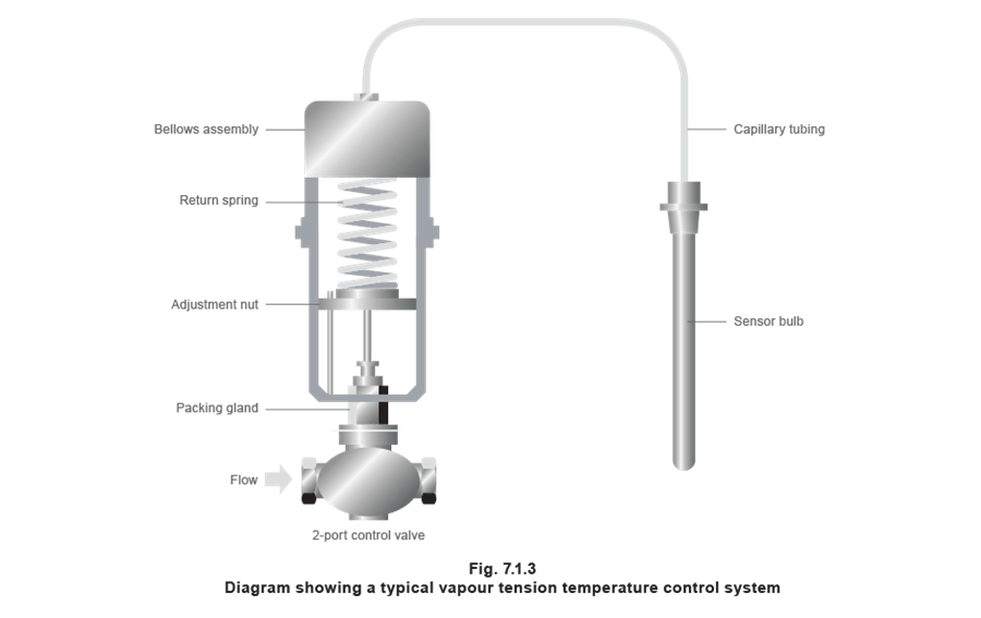
A vapour tension control system has a sensing system filled with a mixture of liquid and vapour. An increase in the sensor temperature boils off a greater proportion of the vapour from the liquid held within it, increasing the vapour pressure in the sensor and capillary system. This increase in pressure is transmitted through the capillary to a bellows or diaphragm assembly at the opposite end (see Figure 7.1.3).
A vapour tension system follows a unique pressure / temperature saturation curve for the fluid contained by the system. All fluids have a relationship between pressure and their boiling temperature. The result can be plotted by a saturation curve. The saturation curve for water can be seen in Figure 7.1.4.
Figure 7.1.4 illustrates how a 5°C temperature change at 150°C will cause a 0.65 bar change in system pressure. At the bottom of the scale, a 5°C temperature change only results in a 0.18 bar change in system pressure. Thus for the same temperature change, the valve will move a greater amount at the top end of the temperature range than at the bottom end.
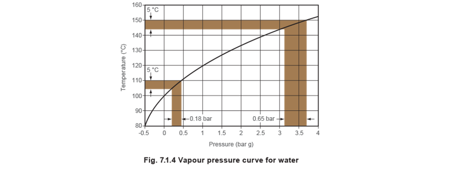
Therefore to move a valve from fully open to fully closed requires a greater temperature change at the bottom end of the range than at the top. Manufacturers of these types of vapour tension control systems often suggest that the control be used only at the top end of its range, but this means that to cover a reasonable temperature span, different fills are used (including water, methyl alcohol and benzene).
Alternatively, a liquid filled system will give a true linear relationship between temperature change and valve movement, largely due to liquid being incompressible. The set temperature can be calibrated in degrees and not simply by a series of numbers. There is no confusion over adjusting the set temperature; which reduces commissioning time. Also, adjustment, which is carried out by altering the amount of space available for the liquid fill, can be carried out anywhere between the control valve and the sensor. This is not so with vapour tension systems, which can usually only be adjusted at the control valve.
- Vapour tension control valves sometimes leak through the stem. To avoid the extra cost of having a second bellows sealing mechanism, most manufacturers of vapour tension controls use a mechanical seal on the valve stem. These tend to be either too loose, causing leaks; or too tight, causing too much spindle friction and the valve to stick.
- In liquid systems, because the valve movement is truly proportional to temperature change and the valve seal is frictionless, the temperature control has a very high rangeability and can control at very light loads.
Liquid self-acting temperature control valves
The valves for use with self-acting temperature control systems can be divided into three groups:
- Normally open two-port valves.
- Normally closed two-port valves.
- Three-port mixing or diverting valves.
Normally open two-port control valves
These valves are for heating applications, which is the most common type of application. They are held in the open position by a spring. Once the system is in operation, any increase in temperature, detected by the sensor, will cause the fill to expand and begin to close the valve, restricting the flow of the heating medium.
Normally closed two-port control valves
These valves are for cooling applications. They are held in the closed position by a spring. When the system is in operation, any increase in temperature will cause the fill to expand and begin to open the valve, allowing the cooling medium to flow.
Force required to close a self-acting control valve
The required closing force on the valve plug is the product of the valve orifice area and differential pressure as shown in Equation 7.1.1. Note that for two-port steam valves, differential pressure should be taken as the upstream absolute steam pressure; whereas for two-port water valves it will be the maximum pump gauge pressure minus the pressure loss along the pipe between the pump and the valve inlet.

Example 7.1.1
Calculate the force required to shut the valve if a steam valve orifice is 20 mm diameter and the steam pressure is 9 bar g. (The maximum differential pressure is 9 + 1 = 10 bar absolute).

This means that the actuator must provide at least 314 newton to close the control valve against the upstream steam pressure of 9 bar g.
It can be seen from Example 7.1.1 that the force required to shut the valve increases with the square of the diameter. There is a limited amount of force available from the actuator, which is why the maximum pressure against which a valve is able to shut decreases with an increase in valve size.
This would effectively limit self-acting temperature controls to low pressures in sizes over DN25, if it were not for a balancing facility. Balancing can be achieved by means of a bellows or a double seat arrangement.
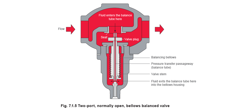
Bellows balanced valves
In a bellows balanced valve, a balancing bellows with the same effective area as the seat orifice is used to counteract the forces acting on the valve plug. A small hole down the centre of the valve stem forms a balance tube, allowing pressure from upstream of the valve plug to be fed to the bellows housing (see Figure 7.1.5). Similarly, the forces on the valve plug pressurise the inside of the bellows. The differential pressure across the bellows is therefore the same as the differential pressure across the valve plug, but since the forces act in opposite directions they cancel each other out.
The balancing bellows may typically be manufactured from either:
- Phosphor bronze.
- Stainless steel, which permits higher pressures and temperatures.
Double-seated control valves
Double-seated control valves are useful when high capacity flow is required and tight shut-off is not needed. They can close against higher differential pressures than single seated valves of the same size. This is because the control valve comprises two valve plugs on a common spindle with two corresponding seats, as shown in Figure 7.1.6. The forces acting on the two valve plugs are almost balanced. Although the differential pressure is trying to keep one plug off its seat, it is pushing the other plug onto its seat.
However, the tolerances necessary to manufacture the component parts of the control valve make it difficult to achieve a tight shut-off. This is not helped by the lower valve plug and seat being smaller than its upper counterpart, which enables removal of the whole assembly for servicing.
Also, although the body and the valve shuttle are the same material, small variations in the chemistry of the individual parts can result in subtle variations in the coefficients of expansion, which adversely affects shut-off. A double-seated control valve should not be used as a safety device with a high limit safeguard.
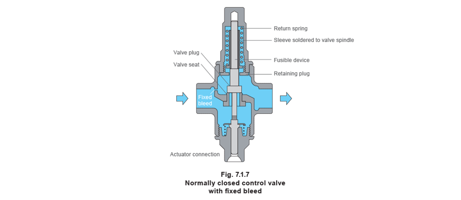
Control valves with internal fixed bleed holes
A normally closed valve will usually require a fixed bleed (Figure 7.1.7) to allow a small amount of flow through the control valve when it is fully shut. Normally closed self-acting control valves are sometimes referred to as being reverse acting (RA).
A typical application for this type of valve is to control the flow of cooling water (coolant) for an industrial engine such as an air compressor (Figure 7.1.8). The control valve, controlling the flow of coolant through the engine, is upstream of the engine and the temperature sensor registers its temperature as it leaves the engine.
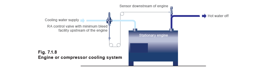
If the coolant leaving the engine is hotter than the set point, the control valve opens to allow more coolant through the valve. However, once the water leaving the engine reaches the required set temperature the valve will shut again. Without a bleedhole, the coolant would no longer flow and would continue to pick up heat from the engine. Without the downstream sensor detecting any temperature rise, the engine is likely to overheat.
If the control valve has a fixed diameter bleed hole, enough cooling water can flow through the valve to allow the downstream sensor to register a representative temperature when the valve is shut. This feature is essential when the sensor is remote from the application heat source.
A normally closed valve might also have an optional fusible device (see Figure 7.1.7). The device melts in the event of excess heat, removing the spring tension on the valve plug and opening the valve to allow the cooling water to enter the system. It is usual with this kind of safety device, that once the fusible device has melted, it cannot be repaired and must be replaced.
Three-port control valves
Most of the control valves used with self-acting control systems are two-port. However, Figure 7.1.9 illustrates a self-acting piston type three-port control valve. The advantage of this type of valve design allows the same valve to be used for either mixing or diverting water applications; this is not normally the case with valves requiring electric or pneumatic actuators.
The most common applications are for water heating, but three-port control valves may also be used on cooling applications such as air chillers, and on pumped circuits in heating, ventilating and air conditioning applications.
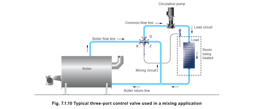
When a three-port control valve is used as a mixing valve (see Figure 7.1.10), the constant volume port ‘O’ is used as the common outlet.
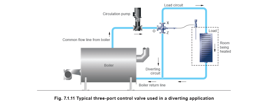
When a three-port control valve is used as a diverting valve (see Figure 7.1.11), the constant volume port is used as the common inlet.
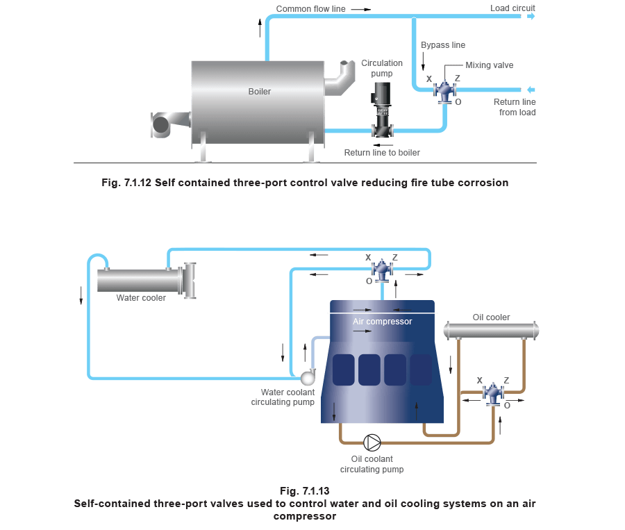
Self-contained three port control valve
Another type of three-port self-acting control valve contains an integral temperature sensing device and thus requires no external temperature controller to operate.
It can be used to protect Low Temperature Hot Water (LTHW) boilers from fire tube corrosion during start-up sequences when the temperature of the secondary return water is low (see Figure 7.1.12). At start-up, the valve allows cold secondary water to bypass the external system and flow through the boiler circuit. This allows water in the boiler to heat up quickly, minimising the condensation of water vapour in the flue gases. As the boiler water heats up, it is slowly blended with water from the main system, thus maintaining protection while the complete system is brought slowly up to temperature.
This type of control valve may also be used on cooling systems such as those found on air compressors (Figure 7.1.13).